Here is part 1: FreeCAD Tutorial Office Chair Part 1: Setup and Constraints
Or go to the previous part.
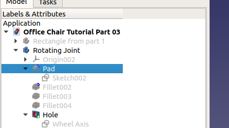
Rotating Joint
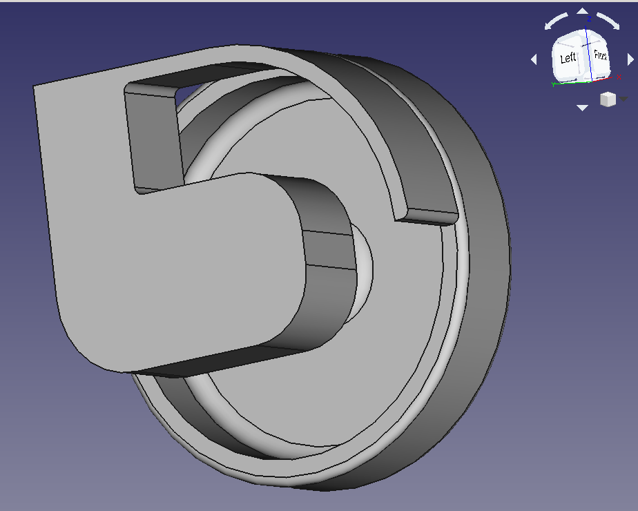
To attach the wheels to the chair’s base, we need a rotating joint like so:

As usual, create a new body, add a sketch. This time, I’m going to use the YZ plane because that will feel most natural when padding (extruding) it:

You can click on the name on the left or the rendering of the plane in the 3D view. In this case, it’s easier to do in the 3D plane since that gives you an immediate idea where you’ll work.
Note that I keep the wheel visible this time so I can see that everything lines up properly.

Hm. I can’t see what I’m doing … That’s the problem with 3D. Now I could make the wheel invisible but I don’t want to (see above). If only I could turn this around … and I can. Notice the white stuff in the top right corner with the word “Right” on it? That means we’re in the “Right Side view”. We want the opposite, the “Left Side view”. You can go there with the items in the menu “View” / “Standard Views” / “Left” or by pressing the “6” key or by using the icons in the toolbar:

… Okay, where is everything???? Probably somewhere outside of the visible volume. How to fix? Menu “Views” / “Standard Views” / “Fit all” or by clicking the toolbar button. The shortcut “V, F” didn’t work for me (it activates the fillet tool).

Much better.
Design this outline:

When I was at this stage, I had a weird bug: I couldn’t select points anymore. If you look closely, you can see that the “lines” are rendered over the “points”:
It’s this “feature”: https://forum.freecadweb.org/viewtopic.php?t=36202
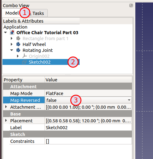
To fix, go to the “Model” tab, select the sketch and change the value for “Map Reversed” to “true”:

This is an instance where you notice that you’re in a 3D world. If lines and points were at the same “depth”, it would be hard to distinguish between them. That’s why the software draws points “above” the lines which literally translates to a different Z position. If you look at this from behind, it will look the other way around: The line will be “before” or “above” the point.
The view should now look like this:

or rather:

sigh Instead of just switching the depth of lines and points in the outline, they flipped the whole thing.
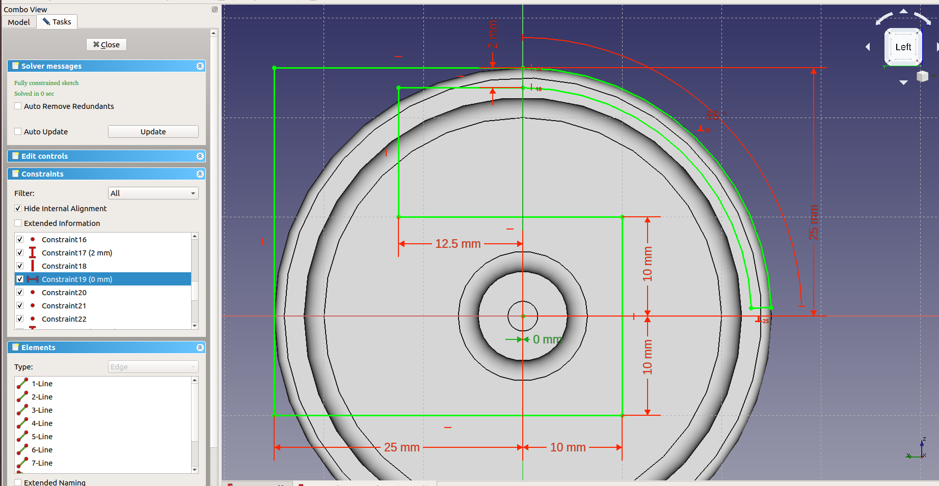
Oh well. Here is the fully constrained outline:
 Some pointers:
- The two starting points of the arcs at the top are horizontally constrained to the Y axis with a distance of 0 mm.
- I’ve constrained the outer arc to 88 ° (always 90 ° is so boring). To make the inner arc do the same, I’ve constrained the closing line to be perpendicular to the outer arc.
- All endpoints are constrained to another
Close the sketch when you’re happy and go back to the “Part Design”. With the “Rotating Joint” active, click “Pad a selected sketch” to get this:

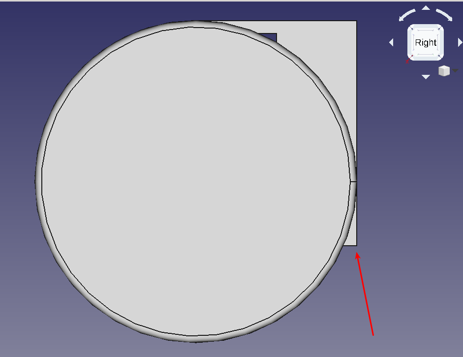
There are a couple of minor and major problems with this. First, lot of hard edges. But more importantly, the lower part stands out:

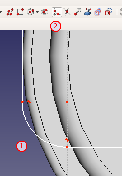
Open the sketch again and add a fillet by selecting the corner and clicking the icon:

This gives us 2 degrees of freedom.
One because we lost a constraint (25 mm distance from origin for the left side) and the other one is the radius of the fillet.

Constraining the center of the fillet to the X axis gives a nice smooth transition from the vertical shaft to the axis. Close the sketch to get this:

Not bad. A couple more fillets:

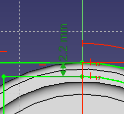
This brought up a problem: I can’t apply a fillet to the inside of the “cover” because the software gets confused when two 1 mm fillets are applied to material that is 2 mm thick.
To fix this, go back to the sketch, change the thickness to 2.2 mm:

and try again:

Much better.
As can see, having to set up all those constraints is a pain in the beginning. But later on, when you find out you have to go back and fix something, it’s a huge time saver. Since you’ll always find mistakes late in the design, this really helps.
Rotate it around in the 3D view. Looks good, doesn’t it?
But it’s not finished. We’re missing an axis, the opposite wheel and a hole for the axis.
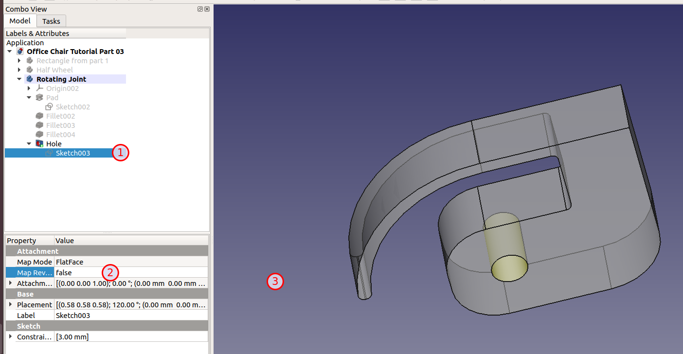
To drill a hole (or any shape) through a volume, create another outline inside of the same body (“Rotating Joint” is still active) and then use the use the “Hole” tool.
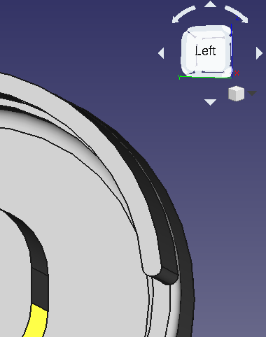
Now, the “Fillet004” (in my case) is in the way. We can’t see anything. Toggle it’s visibility. Again, go to the “Left” view and set “Map Reversed” of the new sketch to “true”.
Pick the circle tool, make sure you click on the origin (it will light up) and pull out the circle.
Select the circle and constrain the diameter (not the radius!) to 3 mm. It should now look like this:

Close, select the sketch and click the “Hole” tool to get this:

Mother of all scary dialogs, creating nothing from something is darn complicated … ahem
Here is the whole documentation for this monster: https://www.freecadweb.org/wiki/PartDesign_Hole
Why is it so complicated? Well, in the real world, holes can be drilled (metal) or formed (plastic when it’s pressed into a form). When drilling, the tip of the hole isn’t straight unless you use a special drill or maybe a mill. Also, some holes go all the way through while other are just depressions.
What’s worse, there is no hole. I’ve toggled visibility of the wheel and made the joint partly transparent (Right click on “Rotating Joint” / “Appearance…” / Transparency: 40). I see the circle but not hole:

So what’s going on here? Remember the “Map Reversed”? Yes, it’s interfering right now. Basically, the hole is there but it points away from the joint (into the wheel). It’s not cutting the wheel since the wheel is a different body and there is no connection between the two. That’s why the hole has no visible effect.
If we select the sketch, switch “Map Reversed” back to “false” and then click somewhere (if you’re using the keyboard: Press TAB once), we get our hole:

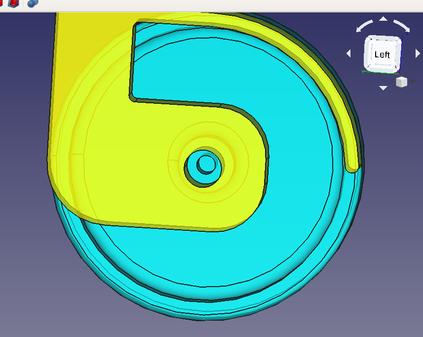
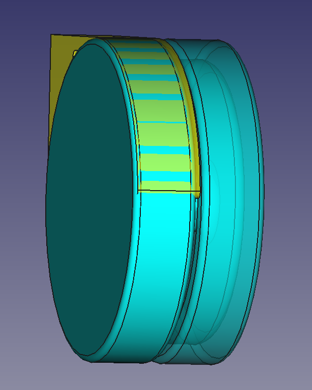
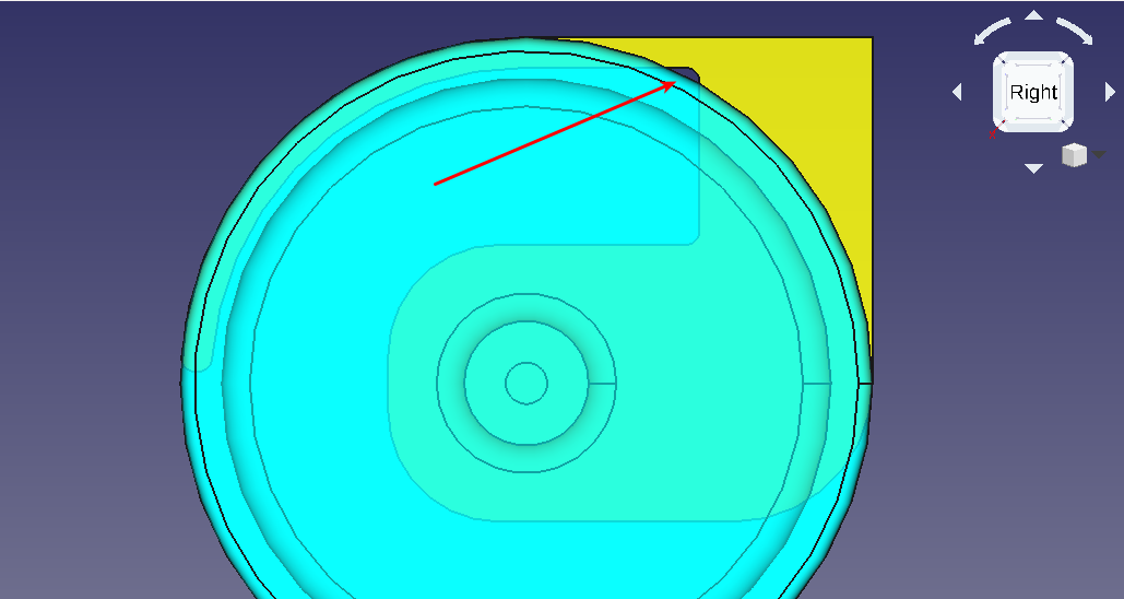
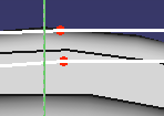
But there is something odd. When rotating the view around (I’ve colored the wheel blueisch and the joint yellow), the holes don’t line up properly:

It looks as if the two holes have different diameters. Why? In the wheel sketch, we used the formula to get 3/2 mm. In the outline for the hole, we used 3 mm diameter. So what is the problem?
Answer:

Why do we have to give a diameter here when we have a profile? Leave a comment when you find out.
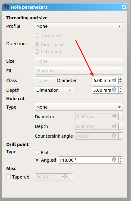
Here is the solution:
- Switch “Depth” to “Through all” to avoid other nasty surprises
- Set “Diameter” to “3 mm”

Come to think of it, 3 mm axis for a chair seems kind of … thin. But I don’t want to change it since it’s in several places already. This isn’t good. What if someone wants to replace the axis with a weaker material and we suddenly need 0.1 mm more? As we’ll see, there is a solution for that as well. For now, let’s stick with the 3 mm axis.
All right. We have a wheel, we have a joint and a hole. Time for the second (mirror) wheel.
Select the “Half Wheel”, chose the mirror tool, select the feature “Wheel Revolution” and … ???

The orientation looks wrong but why is it yellow?
Five minutes later Okay, none of the planes work. What’s going on here?
Hint: Go back to “Model”:

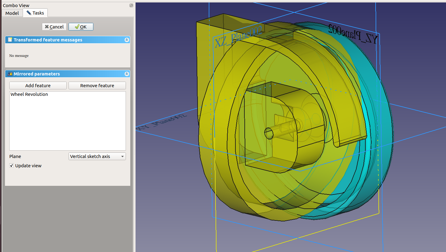
That looks wrong. Mirrored should be part of “Half Wheel”, not the joint. What happened? Well, “Rotating Joint” is active (= bold), therefore the operation is added to it.
Undo. Double click “Half Wheel”. Mirror. Um … better?

But when you click around, you quickly get an error “Transformation failed” and “One transformed shape does not intersect support”. In a nutshell: The “Part Design” workbench can only create connected parts. In our case, there is a gap between the two wheels. They will eventually be connected by a metal axis but that’s not really part of the wheel.
What now?
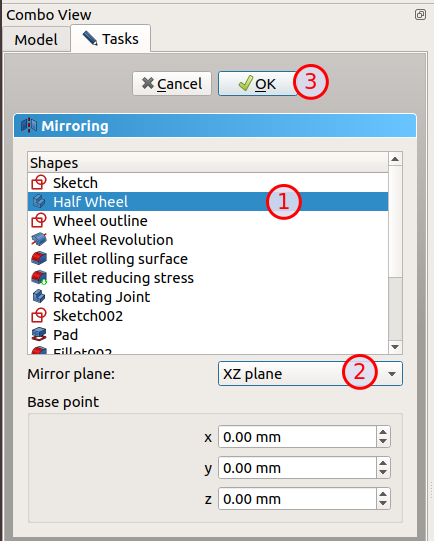
We need a different workbench: “Part”. It has another mirror tool which doesn’t work in features but parts:

If you think about it, it makes sense: When the wheel is assembled, you will get two plastic wheels per foot.
Let’s try again. Click the tool, select the “Half Wheel”, the correct (YZ) plane (which is the one in which we designed the joint sketch):

Click OK to get:

The color looks good and all the fillets are there (they were gone when we used the feature mirror tool). But it’s inside the joint. What’s wrong, now?
If you remember in part 2, we designed the wheel outline to be 1 mm away from the Y axis:

When we mirror that on the Y axis, we get something which is again only 1 mm away from it. But we need 10 mm for the joint.
There are several solutions:
- We could offset the mirror copy by 1 cm using “Placement”
- We could move the original “Half Wheel” (not the outline) 5 mm away from the origin using “Placement”
Let’s try the second solution:
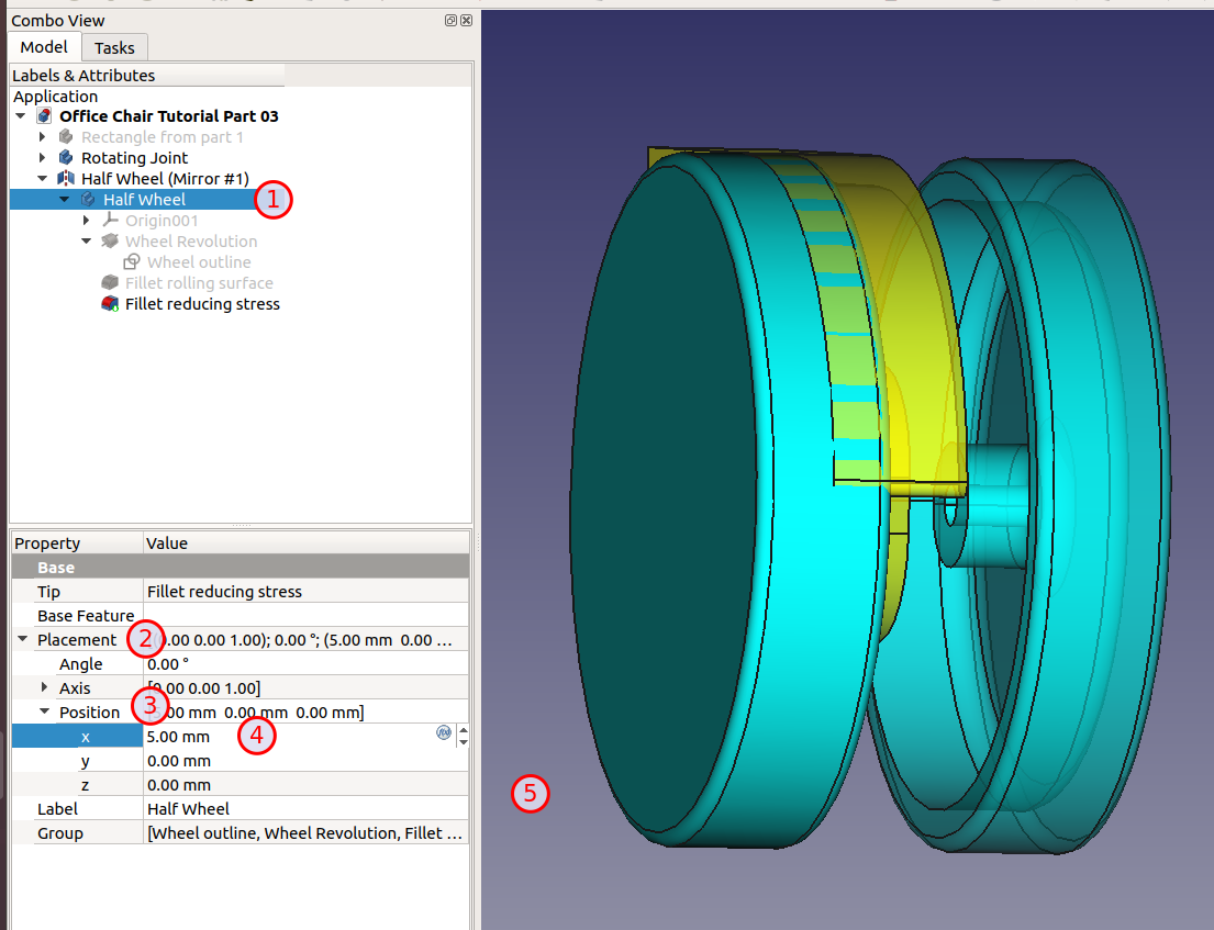
- Select “Half Wheel”
- Open “Placement”
- Open “Position”
- Change the “x” value to “5 mm”
- Click somewhere or TAB out of the field

Already much better. Both wheels moved away from the origin by changing only a single value. Neat.
That leaves us with centering the joint.
Open “Rotating Joint”, double click “Pad”

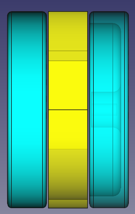
Check “Symmetric to plane”

to get:

Nice. From the top:

No contacts all the way through. But we have an ugly hole when looking at it from the right:

That asks for a bigger fillet. Try 5 mm:

Last step: The rotation axis of the joint (at the top).
- Double click “Rotating Joint” to activate it
- Create sketch
- Use the XY plane
- Make sure you’re in the “Top” view
- Hide the “Hole”
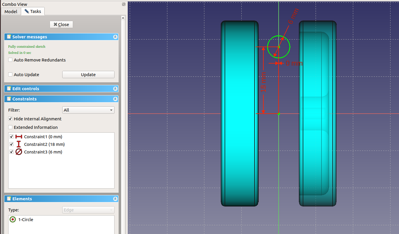
- Draw a circle near the top between the two wheels
- Constrain to Y axis (0 mm distance)
- Constrain vertically to X axis (18 mm)
- Diameter: 6 mm
The result should look like this:

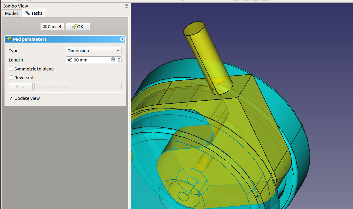
Pad to 45 mm:

Change the node name to “Vertical Joint Axis”
Select the top circle and click the “Chamfer” too to get:

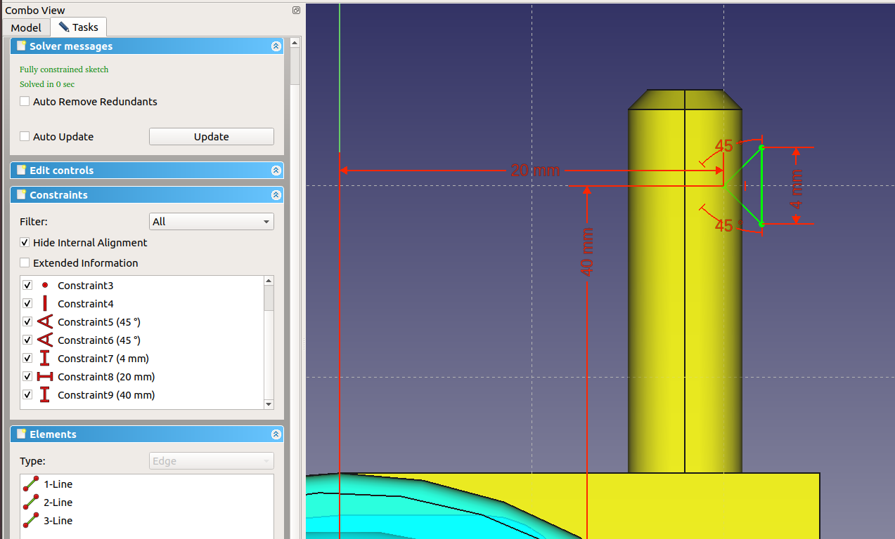
Finally, let’s cut a ring into the vertical axis so we can use a spring to keep it in the socket.
- Create a new sketch
- Use the “YZ” plane
- Use polyline to draw a triangle which bites into the axis near the end

Rename it to “Groove Outline”
Next, I need to rotate this “Groove Outline” around the center axis of the cylinder. There is no such axis but we can create one. In the “Part Design” workbench is a tool “Datum line” for this purpose.
Click on the circle where the cylinder and the joint meet (1) to get a faint yellow line (2):

This gives us the rotation axis that we need. Click OK to save the new “DatumLine”. Rename it to “Vertical Rotation Center”
- Select “Groove Outline”
- Click the “Groove a selected sketch” in the toolbar (1)
- Chose “Select reference…” for “Axis” (2)
- Click on the datum line (3)

and you should already see the groove. Click OK and we’re done:

Here is the file so far: Office Chair Tutorial Part 03
Next part: FreeCAD Tutorial Office Chair Part 4: Five Struts and One Receptacle


 Posted by digulla