Here is part 1: FreeCAD Tutorial Office Chair Part 1: Setup and Constraints
Overview
What’s an office chair without wheels? A wreck. So let’s give them some:

And done. In our next part, we’ll see how we can create the whole foot (two wheels with an axis and a rotating joint to attach to the base) … What?
All right.
As with the rectangle from part 1, we need an outline for the wheel. But before we can start, what should we do with the rectangle itself? We could delete it or create a new project or rename it. I suggest to rename it so you have something handy where you can play around.
Select the node “Body” and press F2 or right click and select “Rename”. Just start typing the new name. That solves half of the problem.
Sketching an Outline
With that out of the way, we need a new body for the wheel. Make sure you’re in the “Part Design” workbench

“Part Design” workbench selector
and click “Create new body”. You might get an error:

That happens when you create a new body while another is currently “active”. Most operations work on the active body. That way, you don’t have to select the target of your operations all the time. Just click OK to get a new, active “Body001”.
Rename it to “Half Wheel”. Why half? It’s good practice to be lazy. Since most chairs have symmetrical wheels (one on each side of the joint), we’ll just draw one of them and then ask the software to create a mirror copy:

Neat, right?
With the body “active” (= the name is bold), create a sketch. If the “Half Wheel” isn’t active, double click on it.
Again, we chose the XY plane:

Hm. I don’t know about you, but I don’t want to see the rectangle while I’m working elsewhere. If we could just hide it … yes, we can.
Go back to the “Model” tab, right click on the rectangle node and select “Toggle visibility” (shortcut: Space):
Much better! Pick the polyline tool and create a rough outline:

The bottom will become a hole for the axis of the wheel, the top is the surface on which the wheel is rolling. As you can see, FreeCAD already created a ton of constraints: Horizontal, vertical and “fix point on object” ones. In my case, it’s already complaining:

I clicked on the link in the solver message “(click to select)” and the offending constraints are green. It’s a vertical constraint in the top left and a horizontal constraint in the bottom right.
I could delete them but I feel those constraints are correct. Instead, the “fix point on object” constraints might be wrong because my outline has no freedoms left in it. If I pick the right side, I can’t move it because the bottom point is nailed to the X axis. Since the dimensions are most certainly wrong, this is bad. Also, the wheel will be stuck in something. Imagine an axis going through the origin. This axis will be in some kind of holder. If the wheel touches the Y axis, it will probably touch whatever holds the axis. We don’t want that kind of grinding, so we have to move the four points on the Y axis away and the “point on object” constraints prevent this.
Let’s delete all of these constraints:

Using Dimensions
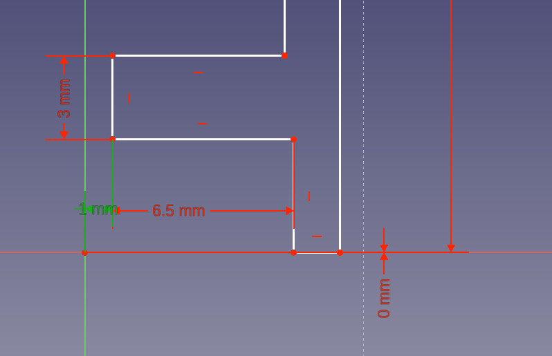
Ah … freedom. Ahem. Let’s start with some simple constraints to get the sizes roughly right. The rolling surface will take all of the weight, so let’s give it 3 mm. The same is true for the material holding the axis. The “side” of the wheel will just take pressure along the material (no torsion), so it can be 2 mm. To save material on the (metal) axis, let’s not extend it all the way out to the side of the wheel. Let’s make the wheel 10 mm thick and 50 mm tall. With these dimensions, we can make the hole for the axis 6.5 mm deep. Deep enough for a good hold:

Note that the height is half of 50 mm = 25 mm.
But it doesn’t look great. Click on the dimensions (the numbers) and drag them until you can read everything properly:

Much better. The 2 mm at the top isn’t great but good enough for now. Let’s move the wheel outline to the correct position. The two bottom dots should be anywhere on the X axis. To achive this, select one of them and the origin and constrain the vertical distance to 0 mm:

Above, we said that we want the wheel to be away from the holder of the axis. Select one of the two vertical points near the bottom left and constrain the horizontal distance to the origin to 1 mm:

sigh Wrong way again. To fix:
- Delete the constraint
- Move the vertical line to the other side of the Y axis
- Apply the constraint again
While dragging the line, you’ll notice two things:
- The whole “box” at the bottom moves along
- The side and rolling surface stay in place
FreeCAD tries to do what you want with the least amount of change.
Using Formulas
Let’s finish the hole for the axis. For this, we need to assign a height. For a 3 mm axis, this would be 1.5 mm. Which we could calculate in our head but how about an axis which is 7.125 mm? To spare use the humiliation, let’s use the little “f(x)” button in the text box. The formula would be “3/2”:
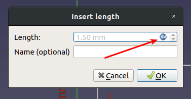
Nice:

To denote the fact that this is a calculated value, the constraint has an orange color. This leaves me with a single degree of freedom left. If you look closely, you’ll see that the bottom and top parts have different widths. If you click on the outline and drag it, you can see that the freedom is only in the length of the horizontal lines at the bottom. There are different ways to fix this:
- We could give the the bottom a total width of 10 mm
- We could constrain the length of the white line on the X axis
- We could constrain the length of the second of the four horizontal white lines (from the bottom)
- We could constrain the horizontal distance between the two leftmost vertical lines
I’ll go for the last approach because that allows us to easily modify the width of the wheel and the gap between wheel and axis holder and, later, the top cover of the wheel:
 I used a 0.5 mm horizontal constraint.
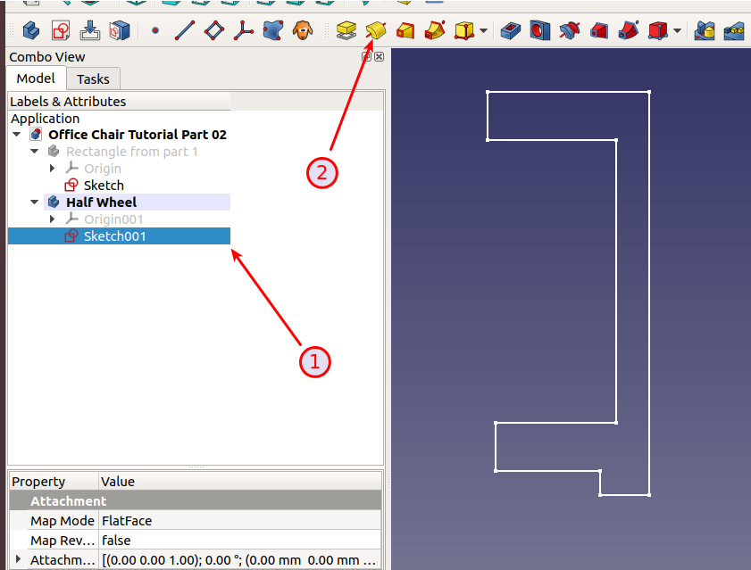
FreeCAD is happy with the result and so am I. Close the outline to go back to the “Part Designer”
Revolve
To turn the outline into a wheel, use the tool “Revolve a selected sketch”. The sketch should be selected; if not, make sure it is:
Now that doesn’t look right:

By default, FreeCAD rotates around the vertical sketch axis (see the “Axis” combobox). Change that to “Horizontal sketch axis” and you have a wheel:
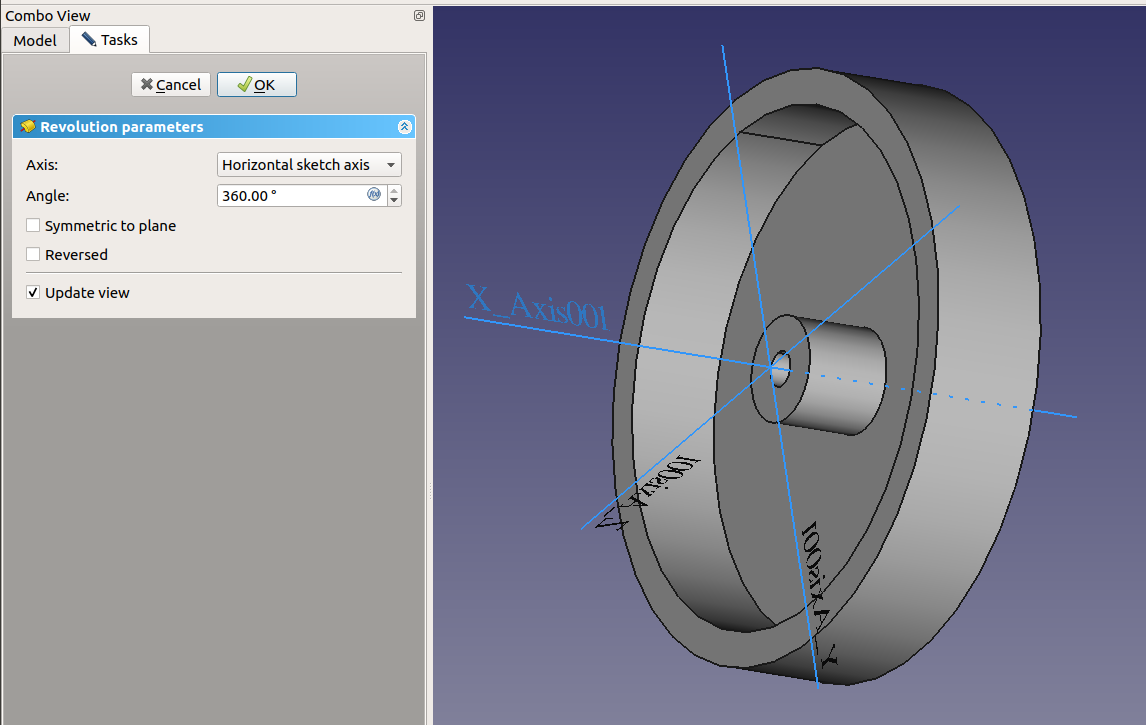
Make sure the rotation angle is 360 (= full circle) and “Symmetric to plane” and “Reversed” are both off.
After clicking OK, our tree looks like this (I’ve opened the “Revolution” node):

As you can see, FreeCAD remembers our operations: We started with the sketch (outline), then rotated it.
Fillets
As wheels go, this one is nice but the edges are too sharp. They would feel bad to the touch and would easily break (they would also be very hard to produce). Let’s round them. Select the rim and click the fillet tool:
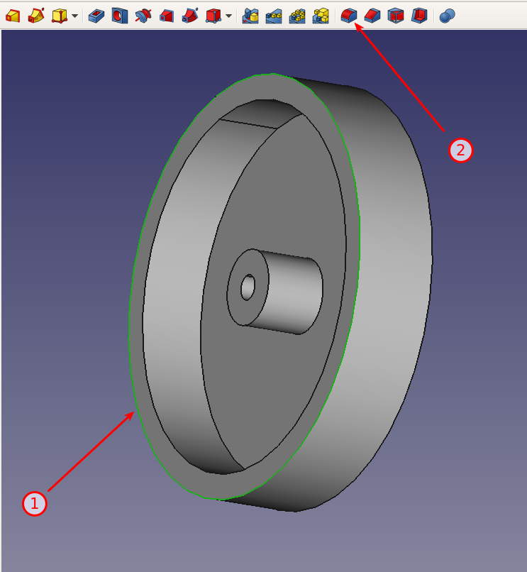
That looks much nicer:

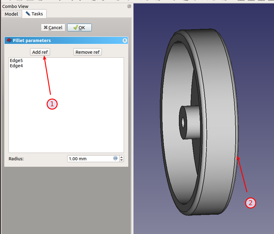
Since we want the same fillet on the outside, click “Add ref”, select the other rim to get:
Now for another fillet on the inside (1) with a radius of 3 mm (2):

Too much? Double click “Fillet001” and change the radius to 2 mm:

Now, I want the same on the axis hole. Double click the fillet again and add the additional edge:

All right. This looks like a nice wheel which won’t break easily:

Note that I’ve renamed most nodes to make it easier to tweak the design later.
Project file: Office Chair Tutorial Part 02
Next part: FreeCAD Tutorial Office Chair Part 3: Mirrors and Holes


 Posted by digulla