After starting FreeCAD 0.18, you’re greeted with this windows:

FreeCAD main window
At the top are the toolbars, on the left side are the current model tree and in the center is the main work area.
The main work area contains a tab “Documents” where you can start a new project and see your recent ones and a tab “Help” which gives you access to the online help. If you have two monitors, I suggest to open a web browser on the second screen and open this URL: https://www.freecadweb.org/wiki/Getting_started
Please read the part about “Navigating in the 3D Space” so you know how to move (pan) the drawing board and how to rotate it and, more importantly, how to reset it to a sane state 🙂
New Project
Let’s start with a new project. Click “Create new…” in the “Documents” tab.
This creates an unnamed project. To give it a name, save the file using “File” / “Save…”.
Working with Constraints
FreeCAD has several main concepts. Let’s look at two of them: Sketch and Part. A sketch is the outline of something. After designing it, you can use a 3D operation like “pad” (often called “extrude” in other software) or “revolve” to create a 3D body from the outline. Other operations cut holes into parts or arrange then in patterns.
The result of all those operations on parts is called “body”.
In order to create our wheel, we need a body, first. To create one, select the “Part Design” workbench:

“Part Design” workbench selector
This will give you a new toolbar:

Create body icon
The first icon is the one we want. It will add a node “Body” to the tree with a child “Origin”. This child is the coordinate system of the body. Each body has their own (since they are independent of each other).

Tree with the first body
Tip: Try to design your bodies in such a way that the “handle” (= the must useful point to place the body) is at the origin (0,0,0).
Now that we have a body, we can create our first outline using the second icon. FreeCAD will switch from “Model” to “Tasks” and ask for the plane in which you want to draw:

Select plane in which to draw sketch
FreeCAD is a 3D CAD software but editing 3D with a 2D mouse is tedious and error prone. To work around this problem, the designers of the software came up with a trick: They let you draw the outline of a shape and then give you tools to turn the outline into a volume.
For our wheel, we’ll draw the outline and then rotate it around the wheel’s axis to get a complete wheel.
You will now have to decide in which plane you want to draw the outline. If X is “left-right” and Y is “up-down”, then Z is “closer-farther”. This gives you three planes: XY (what we all used in school), XZ (horizontal or ground plane) and YZ (vertical but perpendicular to XY).
For example, you could think that the wheel stands on the ground, it’s axis parallel to the X axis, and you’re looking down on it. If you think like this, the most natural approach is to cut the wheel horizontally and remove the top part. Now you can see the outline of the wheel in the in the XZ plane.
Or you can think of the wheel as standing in front of you. Now, we cut it vertically along the XY plane to get an outline.
Or you can think of looking at the wheel from the side. In this case, the outline would be in the YZ plane.
Let’s start with XY (XY_Plane) just like in school. After clicking OK, you’ll see the “Sketcher” workbench:
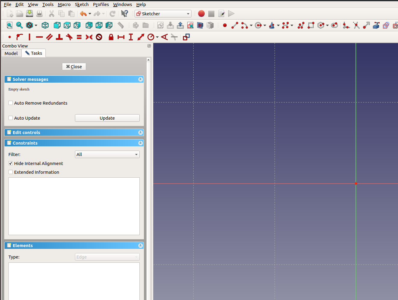
Sketcher Workbench
All this workbench switching probably feels a bit scary. The advantage is that you won’t see thousands of icons.
Tip: You’ll be working a lot with constraints. To make your life easier, pull down the constraint toolbar down like I did to be able to see all icons at once.
To the left are now three panels under “Tasks”: Solver messages, Constraints, Elements.
Elements is a list of basic shapes that make up the outline. That can be lines, arc, circles, polylines, etc.
Constraints lists the properties which must be fulfilled to create a “correct” outline. For example, if you have two lines which must be parallel, the output is wrong when the lines are skewed.
FreeCAD uses a “solver” to determine the correct outline. The topmost panel is used to keep you informed about the success or failure of this process.
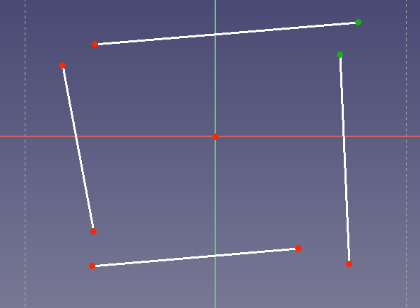
Confused? Let’s start with a simple example and create a rectangle from four lines. Click the “Create a line” tool (shortcut: L). Now click for the first point, move the mouse, click again for the second point. Repeat 3 times to get four lines like so:

Note the little red line next to your cursor. This tells you that the tool is still active. To deactivate it, click the right mouse button once.
But that’s not a rectangle, you say. Why not?
Well, first of all, the corners should be closed. To fix this, I use the “Coincident Constraint” (shortcut: C). Select two points that should have the same position. There are two ways to do this:
- Click and drag a rectangle around two points
- Click on two points.
To clear the selection, click on the blue background of the drawing.
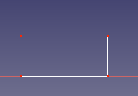
Afterwards, you should have two green points and 7 red ones (6 line ends and one origin):
Click on “Coincident Constraint”:

Two things happen:
- The second point will move to the first one
- A new item “Constraint1” will be added to the list of constraints
Click on the new corner and drag the mouse around to see that the endpoints of the two lines are in fact “connected”.
Repeat with the other three:

Still not a rectangle but closer. What else defines a rectangle?
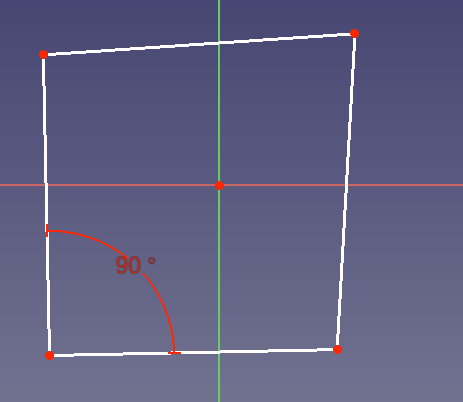
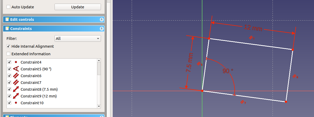
90° angles in the corner. Let’s add this constraint as well. First, select two lines with a common point by clicking on them to turn them green, and then on the “Constraint Angle” icon (1) to get a new dialog which asks for an angle:

As you can see, the tool offers the current angle as default which is great if you just need a small adjustment. Enter “90” and close the dialog with OK. You’ll see a new “Constraint5” in the list with “(90 °)” behind it but the result looks off:
What happened? Well, FreeCAD just made sure those two lines are now at a 90° angle with respect to each other. It didn’t rotate the whole rectangle. This allows you to create rectangles at all angles. To fix the right side, let’s make it parallel to the left side. Select the two sides and click the “Constraint parallel” (icon with two diagonal parallel lines):

Note “Constraint6” plus the small icons next to the vertical lines.
Also notice that the rectangle rotated. Annoying, isn’t it? But we didn’t tell FreeCAD where the rectangle is supposed to be, so it shifts it around to make our demands work.
One side left. To fix it, we have three options:
- We can make it parallel to the bottom edge
- We can add a 90° angle in either corner
- We can assign a length to the left or right side and then add an “equal length” constraint to the other side.
Since less is more, we’ll just add another parallel. But keep in mind that there is often more than one way to get to a result:

Finally, a rectangle (almost a square). But if you look at the “Solver messages” panel, it says “Under-constrained sketch with 5 degrees of fredom”. What does that mean?
It means that while it’s a rectangle, that’s not good enough for CAD purposes. For example, it has no defined width or height. Imagine buying a car where you don’t know the size in advance!
Let’s create a rectangle with is 7.5 mm tall and 12 mm wide.
Select the left side, then click “Fix a length of a line” (1):
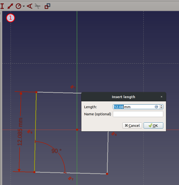
Enter “7.5” and click OK.
You will notice that both the left and right side of the rectangle changed their lengths (and it jumped). This is because of our parallel constraints: FreeCAD will keep the shape for us, even when things change!
Set the width to 12 mm in the same way:

This gets us down to 3 degrees of freedom. In our case, that the X and Y position of the rectangle and the orientation.
It’s good practice to define a “handle” or “attachment” point. In our example, let’s say that the bottom left corner is our attachment point. This point should be at the origin. Select the origin (click on it or use the menu item “Sketch” / “Sketch Tools” / “Select origin”; shortcut: Ctrl+Shift+O), then the bottom left corner of the rectangle and finally “Coincident Constraint”:
To get a feeling how the constraints work, grab a side or corner and drag it around. See how the rectangle keeps it’s shape and only rotates around the bottom left corner?
Almost done. Add an angle constraint of 17.5 ° between the X axis (just click the horizontal line) and the bottom edge:
What happened? Why is it going “down” instead of “up”?
FreeCAD doesn’t count angles from the X axis. It just keeps the angle between the two selected lines by moving everything the least amount. In this case, the downward direction was “closer” and therefore, it used this solution. If you want the other result, delete the constraint (or use undo), rotate the rectangle up and try again:

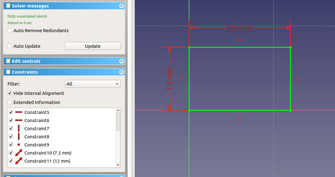
Note that the whole outline turned green to indicate that it’s properly defined, now.
In the Solver panel, you can see “Fully constrained sketch”.
To finish the outline, scroll up in the “Tasks” panel and click “Close”:

Final result as download: Office Chair Tutorial Part 01
Over time, you’ll find better and faster ways to do things in the software. Let’s try it. Draw a rectangle instead of four lines:

Note that the software already filled 8 constraints for you. Constrain the left bottom edge to the origin:
Constrain width and height as above:

And assign an angle of 17.5 ° to the bottom line:

Hey! What’s wrong?
Well, there is a constraint that the bottom edge is parallel to the X axis (the red dash). It’s either Constraint 5 or 6. The solver tells us “Over-constrained sketch” and, helpfully, “Please remove either constraints 6 or 12”. Also, there is a dialog “Negative datum values are not valid for the constraint with index 11”.
The dialog is confusing and not very helpful. Sorry for that. Just close it.
Huh? Everything is fine?
Oh, it just deleted the angle constraint! That’s not what we want. But it already gave us a clue: The “bottom must be horizontal” constraint is #6 (from the error message above). Delete it and try again with the angle constraint:

Well … almost 🙂 Double click on the angle and change it to “-17.5 °”:

We’re getting there. Delete constraint 5 and make top and bottom parallel:
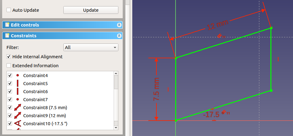
A parallelogram (or rhomboid)! Do you feel the power of the tool? How it tries to fulfill your expectations? Remove the vertical constraints and drag an upper corner of the rectangle around. You probably thought it would slide sideways but instead the corners “rotate” around their bottom counterparts. If you pick the right bottom corner, you can only slide it along the bottom edge, shortening or extending it in the process. That’s what FreeCAD means when it says “2 degrees of freedom”.
To fix this, you need to apply the rules of rectangle (all four corner angles must be 90 °). Let’s start by using a 90 ° constraint in the bottom right corner:
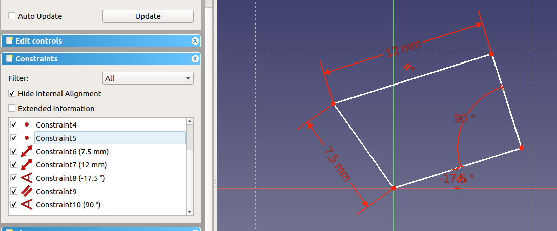
Close. To get the same result as before, we either need to assign another 90 ° constraint or make the left and right side parallel. Let’s add a angle constraint in the top right corner:
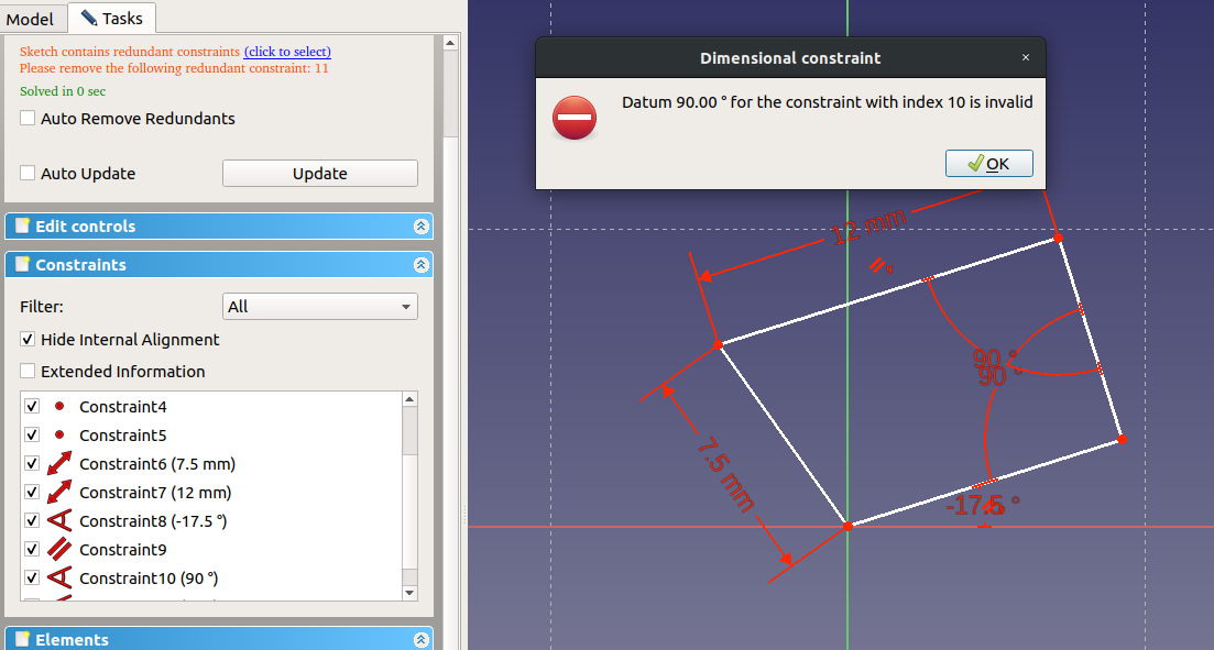
A new error: “Sketch contains redundant constraints” and (another) useless dialog “Datum 90.00 ° for the constraint with index 10 is invalid.” What happened? We have a parallel and two 90 ° constraints. That’s too much; either two 90 ° constraints or one parallel plus one 90 ° constraint would be enough to achieve the same result. In a nutshell, FreeCAD tries to help us avoid unnecessary constraints. For one, they are futile and secondly, they might get in the way later when we want to change something. Clicking OK in the dialog and our angle constraint will be gone. Two to put the 90 ° angle into one of the two left corners:

All right. Same result as above but using a different route. This time, we made more “mistakes” which helped us to understand how constraints can both help and hinder us.
Office Chair Tutorial Part 01 Two Rectangles
In the next part, we’ll use constraints to define the outline of a chair wheel. FreeCAD Tutorial Office Chair Part 2: Wheels

[…] Part 1: Setup and Constraints […]
[…] Here is part 1: FreeCAD Tutorial Office Chair Part 1: Setup and Constraints […]
[…] Here is part 1: FreeCAD Tutorial Office Chair Part 1: Setup and Constraints […]
[…] Here is part 1: FreeCAD Tutorial Office Chair Part 1: Setup and Constraints […]