Upset by all the plastic in the oceans?

Check https://teamseas.org/ for details.
Upset by all the plastic in the oceans?
Check https://teamseas.org/ for details.
 Leave a Comment » |
  Life | Tagged: environment |
  Permalink
 Posted by digulla
we get a potency of impossibilities.
Leave a Comment » | Philosophy, Software | Tagged: Philosophy, Software Development | Permalink
Posted by digulla
Here is part 1: FreeCAD Tutorial Office Chair Part 1: Setup and Constraints
Or go to the previous part.
I fixed the transparency and the hard edges of the joint plus renamed a few nodes:

Here is the file: Office Chair Tutorial Part 04 Start
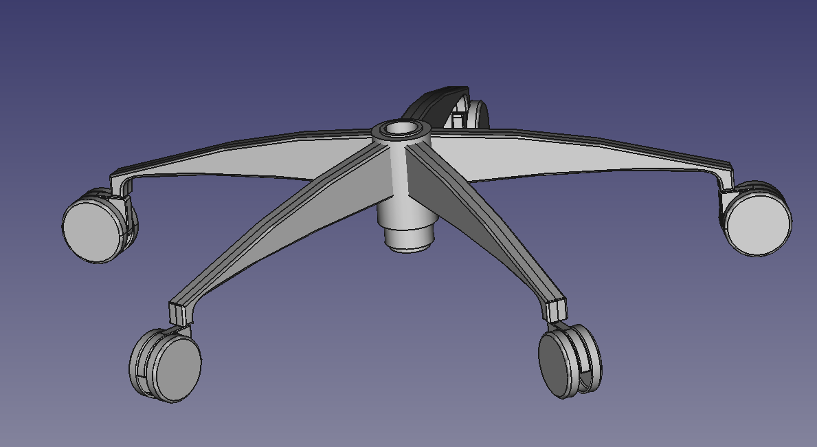
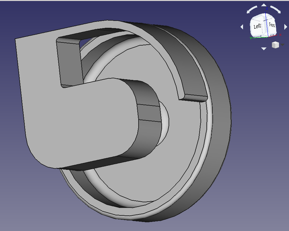
The base of our chair should have five struts and hole to support the gas spring:
Create a new body, call it “Strut”.
Create a sketch, use the same plane as the joint (YZ Plane).
You should end up with this:

Draw a corner around the vertical joint axis:

For the arching strut, we’re going to use two B-splines with control points. For each arch, create three control points (so the whole spline should have 5 points):

Those “fans” look weird, right?
Those visualize how “bent” the spline is (= speed of change of direction, longer lines = faster change). If you have nicks in those curves (like above), it can mean trouble. Let’s ignore those fans for now.
Note how I created a sharper bend by moving two control points closer together (lower spline, two control points to the left).
Make sure that the left end points of both arches are constrained to the end points of the corner.
One thing I would like to do is to constrain the “joint end” of the strut to the “Vertical Rotation Center” which we created in the joint. That way, the strut will keep it’s position relative to the axis of the joint. The problem is that this datum line is part of the “Rotating Joint” body.
To change this:

Double click “Sketch006” to continue working on it.
Try to apply a horizontal constraint between the bottom left edge and the datum line.
Turns out, we can’t select the datum line … now what?
Let’s try a “local coordinate system”.

Hm …. I would prefer the Z axis to go “up”. To achieve this, check “Flip sides”:

Nice. Click “OK” to create the coordinate system.
You’ll get this dialog:

Remember we selected the circle? It’s part of the joint body. FreeCAD now wonders how we want to handle this situation. Do we want to create something which will stay put when we change the joint? Or maybe we just want to use the new coordinate system in the body it references (dependent copy)? Or should changes to the joint move the coordinate system?
We want to last of the options since one end of the arch should stay where the joint is. Select “Create cross-reference” and “OK”.
Hm … there doesn’t seem to be a way to use the new coordinate system in the existing sketch.
I also can’t find a way to use it in a new sketch.
The sketch always asks for a plane. The toolbar offers a datum plane, let’s try that.
I again select the circle, attachment mode is “Concentric” but the new plane is coplanar (= in the same plane) with the circle. We need something that is perpendicular to the circle. Flip sides won’t help this time, set “Roll” to “90 °”:

The orientation looks good but what about the origin? From the preview, the plane seems to be way to far up/right. Let’s hope for the best. OK, “Create cross-reference”, OK.
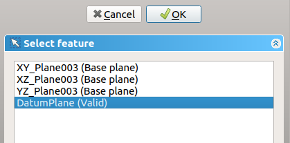
Create a new sketch and now ,we can select our now DatumPlane:
Hm. Why is everything upside down?

3D is annoying. I bet this is because of our 90 ° roll. Edit the plane, select “Flip sides”. If we create a new sketch, this looks much better:
What about our existing geometry? I couldn’t find a way to copy the elements and constraints over, so they are lost. Just make the old sketch visible and draw something similar.
Now for the big moment: Will the constraints use the new origin?
Yes!
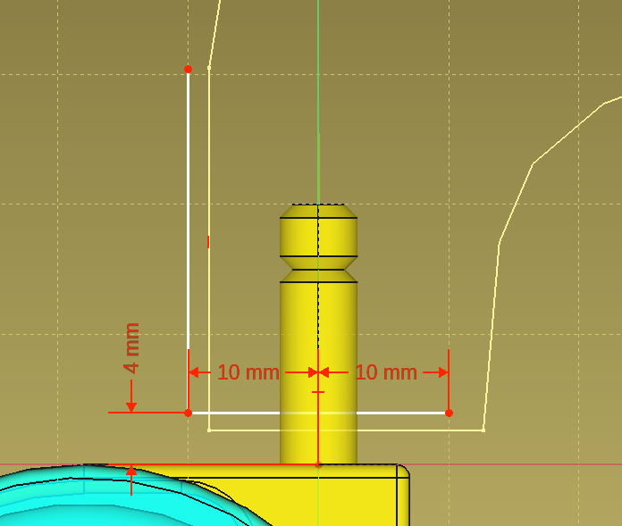
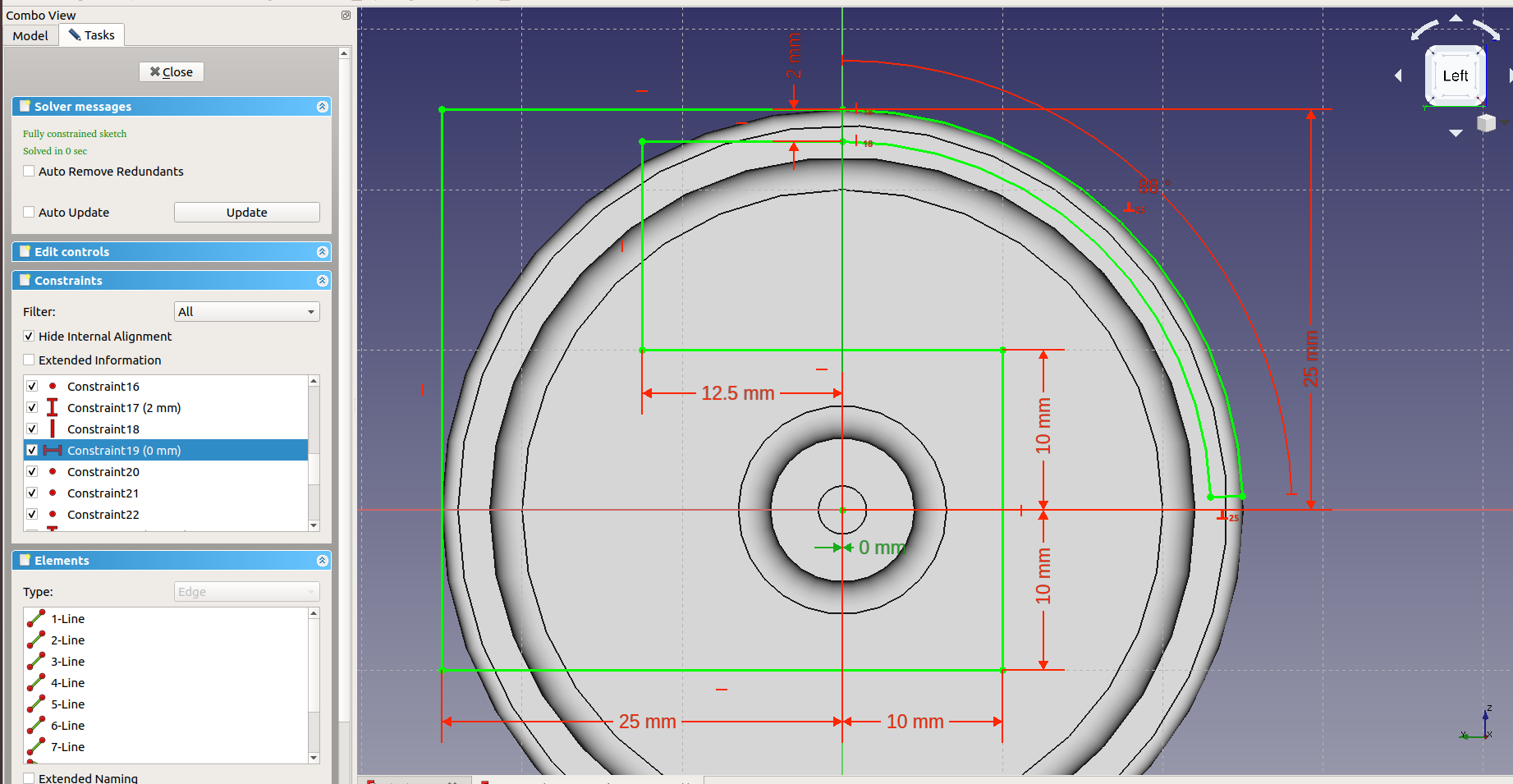
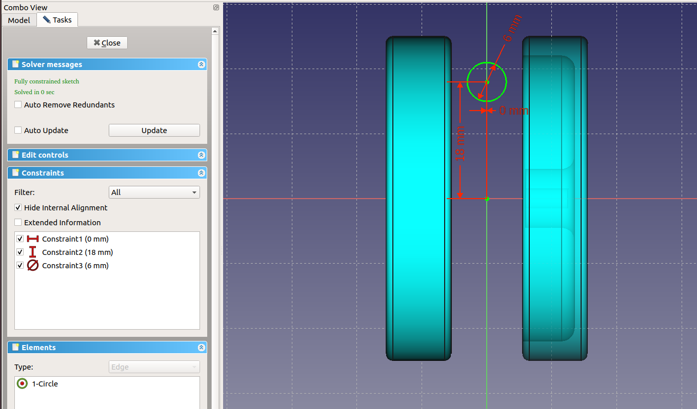
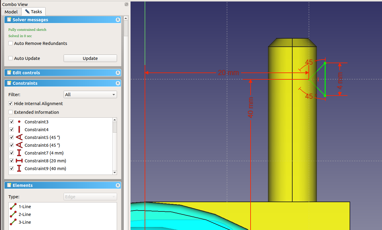
Working from left to right, I get this fully constrained sketch:

The blue distance at the bottom is a constraint in “reference mode” which basically means it just shows a value but doesn’t take part of the solution process:
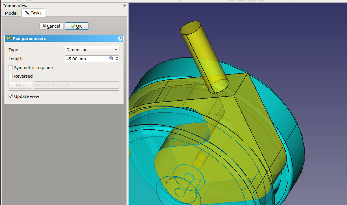
Close the sketch and pad it, 10 mm, symmetric to plane plus some fillets gives me:

For the central socket, we need another datum plane at the far end of the strut. Otherwise, attaching the chair to the base would be complicated.
Note: Another solution would be to join all parts in a compound and then move the compound around until the upper end of the strut is near the origin (right now, it’s just the other way around).
Note 2: Before you design something complicated, you may want to figure out a good place for your origin. Our situation happened because I chose to build the first foot around the origin.
The new datum plane is parallel to the first one but shifted to the right (= positive along the X axis)
I tried several ways to achieve this but I have a feeling that creating work / datum planes is not designed very well at the moment. There are lots of complicated options but nothing that really works well.
In the end, I used this complicated mess:

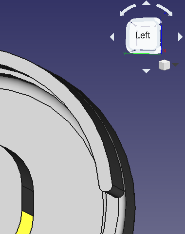
I selected “Plane face” as mode, then clicked on the yellow face. I created a sketch based on this plane. Jumping back and forth between the sketch and the plane, I played with the attachment offsets until it was kind of where I wanted it:

One revolve and a few fillets later, I had this:

The last step is to make five copies of the strut plus foot.
While I could use copy & paste, the copies would be independent. So no change I made to the original would propagate. To solve this, there is a Array tool. This tool can create copies and arrange them, too.
As rotation axis, we need a datum line. Select one of the circles around the socket:

Click OK.
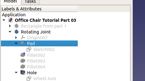
Since we want to copy three bodies (wheels, joint and strut), we first need to combine them into one body.
Your tree should now look like so:

To create five copies:
At least in my version of FreeCAD, this didn’t have a dialog or panel to configure the array. Instead, you get this:
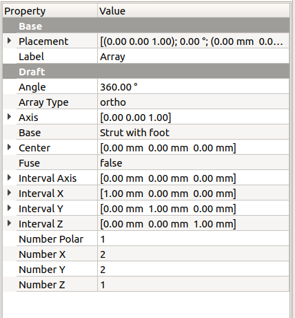
Change these values:
You’ll get this:

Remember when I said that it’s important to decide where to put the origin? That’s why.
Also, there is no way to select a rotation axis (the datum line from above).
How to fix this?
One way is to move the “Strut with foot” so that it’s other end is near the origin. This can be done by changing the “Position”. On my case, the y value:

Okay … better … I guess. What’s with the wheel at the center? Doesn’t want to play with the rest?
Enough for today. Here is the file if you want to fix it yourself: Office Chair Tutorial Part 04
2 Comments | Software, Tutorial | Tagged: CAD, FreeCAD, Software, Tutorial | Permalink
Posted by digulla
This is a multi-part tutorial how to create an office chair with FreeCAD (documentation).
FreeCAD is a parametric 3D CAD software. This means it remembers all the operations you did to come up with a shape. Some of these operations can be modified later, for example if you create a line which is 1 cm apart from another, you can change the distance to 1.5 cm. FreeCAD will then redo everything that happened afterwards to give you the new result.
As we’ll see, this means you’ll have to give precise instructions (even when you don’t know, yet) that you can amend later.
Leave a Comment » | Software, Tutorial | Tagged: CAD, FreeCAD, Software, Tutorial | Permalink
Posted by digulla
Here is part 1: FreeCAD Tutorial Office Chair Part 1: Setup and Constraints
Or go to the previous part.
To attach the wheels to the chair’s base, we need a rotating joint like so:

As usual, create a new body, add a sketch. This time, I’m going to use the YZ plane because that will feel most natural when padding (extruding) it:

You can click on the name on the left or the rendering of the plane in the 3D view. In this case, it’s easier to do in the 3D plane since that gives you an immediate idea where you’ll work.
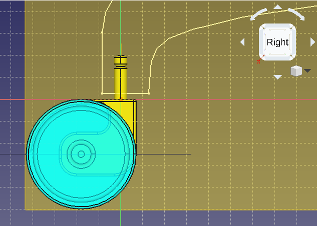
Note that I keep the wheel visible this time so I can see that everything lines up properly.

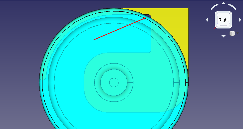
Hm. I can’t see what I’m doing … That’s the problem with 3D. Now I could make the wheel invisible but I don’t want to (see above). If only I could turn this around … and I can. Notice the white stuff in the top right corner with the word “Right” on it? That means we’re in the “Right Side view”. We want the opposite, the “Left Side view”. You can go there with the items in the menu “View” / “Standard Views” / “Left” or by pressing the “6” key or by using the icons in the toolbar:

… Okay, where is everything???? Probably somewhere outside of the visible volume. How to fix? Menu “Views” / “Standard Views” / “Fit all” or by clicking the toolbar button. The shortcut “V, F” didn’t work for me (it activates the fillet tool).

Much better.
Design this outline:

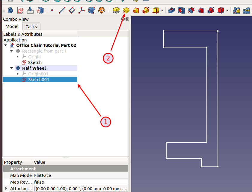
When I was at this stage, I had a weird bug: I couldn’t select points anymore. If you look closely, you can see that the “lines” are rendered over the “points”:

It’s this “feature”: https://forum.freecadweb.org/viewtopic.php?t=36202
To fix, go to the “Model” tab, select the sketch and change the value for “Map Reversed” to “true”:
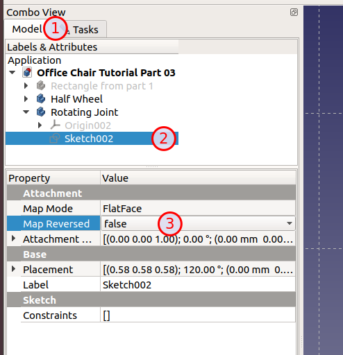
This is an instance where you notice that you’re in a 3D world. If lines and points were at the same “depth”, it would be hard to distinguish between them. That’s why the software draws points “above” the lines which literally translates to a different Z position. If you look at this from behind, it will look the other way around: The line will be “before” or “above” the point.
The view should now look like this:

or rather:

sigh Instead of just switching the depth of lines and points in the outline, they flipped the whole thing.
Oh well. Here is the fully constrained outline:
 Some pointers:
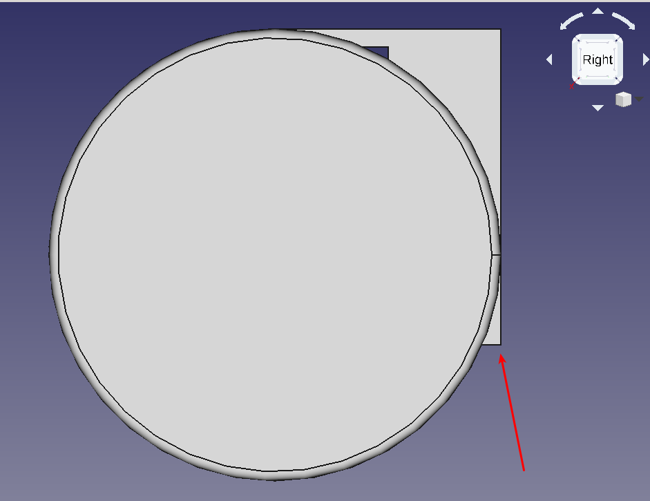
Close the sketch when you’re happy and go back to the “Part Design”. With the “Rotating Joint” active, click “Pad a selected sketch” to get this:

There are a couple of minor and major problems with this. First, lot of hard edges. But more importantly, the lower part stands out:
Open the sketch again and add a fillet by selecting the corner and clicking the icon:
This gives us 2 degrees of freedom.
One because we lost a constraint (25 mm distance from origin for the left side) and the other one is the radius of the fillet.

Constraining the center of the fillet to the X axis gives a nice smooth transition from the vertical shaft to the axis. Close the sketch to get this:

Not bad. A couple more fillets:
This brought up a problem: I can’t apply a fillet to the inside of the “cover” because the software gets confused when two 1 mm fillets are applied to material that is 2 mm thick.
To fix this, go back to the sketch, change the thickness to 2.2 mm:
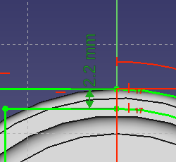
and try again:
Much better.
As can see, having to set up all those constraints is a pain in the beginning. But later on, when you find out you have to go back and fix something, it’s a huge time saver. Since you’ll always find mistakes late in the design, this really helps.
Rotate it around in the 3D view. Looks good, doesn’t it?
But it’s not finished. We’re missing an axis, the opposite wheel and a hole for the axis.
To drill a hole (or any shape) through a volume, create another outline inside of the same body (“Rotating Joint” is still active) and then use the use the “Hole” tool.
Now, the “Fillet004” (in my case) is in the way. We can’t see anything. Toggle it’s visibility. Again, go to the “Left” view and set “Map Reversed” of the new sketch to “true”.
Pick the circle tool, make sure you click on the origin (it will light up) and pull out the circle.
Select the circle and constrain the diameter (not the radius!) to 3 mm. It should now look like this:

Close, select the sketch and click the “Hole” tool to get this:

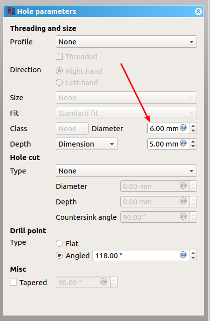
Mother of all scary dialogs, creating nothing from something is darn complicated … ahem
Here is the whole documentation for this monster: https://www.freecadweb.org/wiki/PartDesign_Hole
Why is it so complicated? Well, in the real world, holes can be drilled (metal) or formed (plastic when it’s pressed into a form). When drilling, the tip of the hole isn’t straight unless you use a special drill or maybe a mill. Also, some holes go all the way through while other are just depressions.
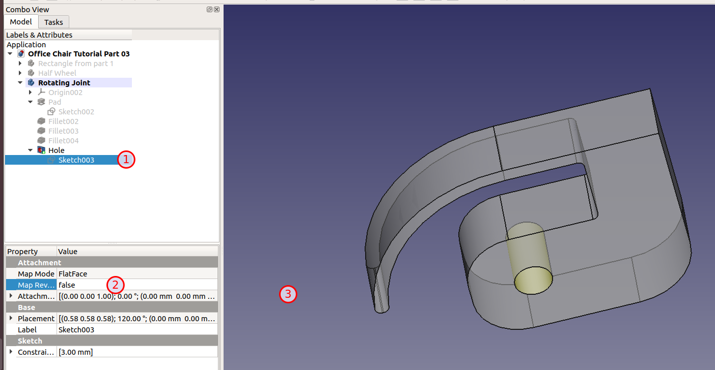
What’s worse, there is no hole. I’ve toggled visibility of the wheel and made the joint partly transparent (Right click on “Rotating Joint” / “Appearance…” / Transparency: 40). I see the circle but not hole:

So what’s going on here? Remember the “Map Reversed”? Yes, it’s interfering right now. Basically, the hole is there but it points away from the joint (into the wheel). It’s not cutting the wheel since the wheel is a different body and there is no connection between the two. That’s why the hole has no visible effect.
If we select the sketch, switch “Map Reversed” back to “false” and then click somewhere (if you’re using the keyboard: Press TAB once), we get our hole:
But there is something odd. When rotating the view around (I’ve colored the wheel blueisch and the joint yellow), the holes don’t line up properly:
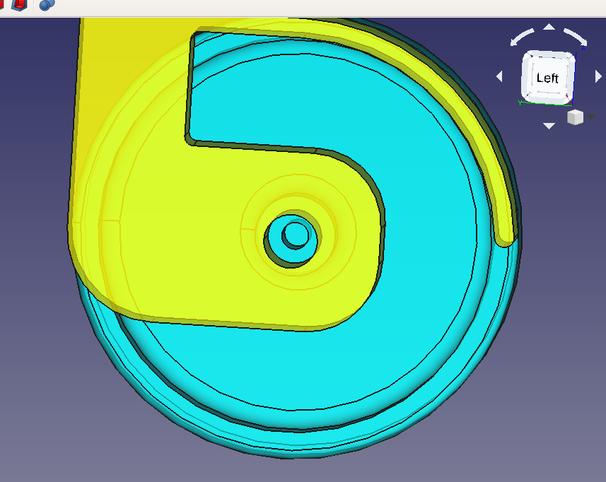
It looks as if the two holes have different diameters. Why? In the wheel sketch, we used the formula to get 3/2 mm. In the outline for the hole, we used 3 mm diameter. So what is the problem?
Answer:
Why do we have to give a diameter here when we have a profile? Leave a comment when you find out.
Here is the solution:

Come to think of it, 3 mm axis for a chair seems kind of … thin. But I don’t want to change it since it’s in several places already. This isn’t good. What if someone wants to replace the axis with a weaker material and we suddenly need 0.1 mm more? As we’ll see, there is a solution for that as well. For now, let’s stick with the 3 mm axis.
All right. We have a wheel, we have a joint and a hole. Time for the second (mirror) wheel.
Select the “Half Wheel”, chose the mirror tool, select the feature “Wheel Revolution” and … ???
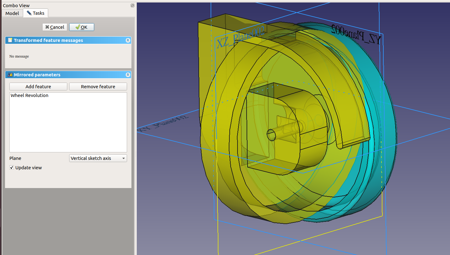
The orientation looks wrong but why is it yellow?
Five minutes later Okay, none of the planes work. What’s going on here?
Hint: Go back to “Model”:

That looks wrong. Mirrored should be part of “Half Wheel”, not the joint. What happened? Well, “Rotating Joint” is active (= bold), therefore the operation is added to it.
Undo. Double click “Half Wheel”. Mirror. Um … better?

But when you click around, you quickly get an error “Transformation failed” and “One transformed shape does not intersect support”. In a nutshell: The “Part Design” workbench can only create connected parts. In our case, there is a gap between the two wheels. They will eventually be connected by a metal axis but that’s not really part of the wheel.
What now?
We need a different workbench: “Part”. It has another mirror tool which doesn’t work in features but parts:

If you think about it, it makes sense: When the wheel is assembled, you will get two plastic wheels per foot.
Let’s try again. Click the tool, select the “Half Wheel”, the correct (YZ) plane (which is the one in which we designed the joint sketch):
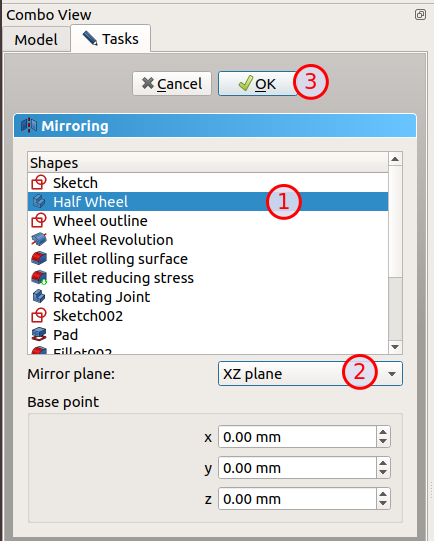
Click OK to get:
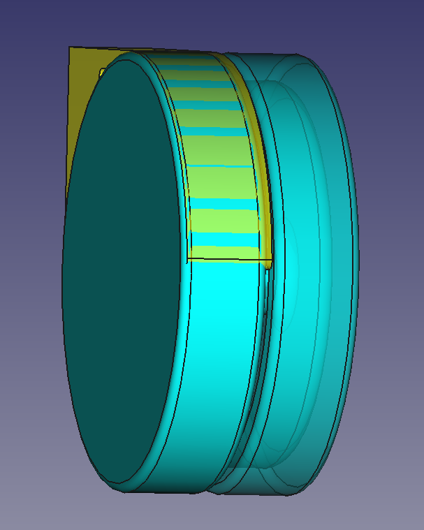
The color looks good and all the fillets are there (they were gone when we used the feature mirror tool). But it’s inside the joint. What’s wrong, now?
If you remember in part 2, we designed the wheel outline to be 1 mm away from the Y axis:

When we mirror that on the Y axis, we get something which is again only 1 mm away from it. But we need 10 mm for the joint.
There are several solutions:
Let’s try the second solution:
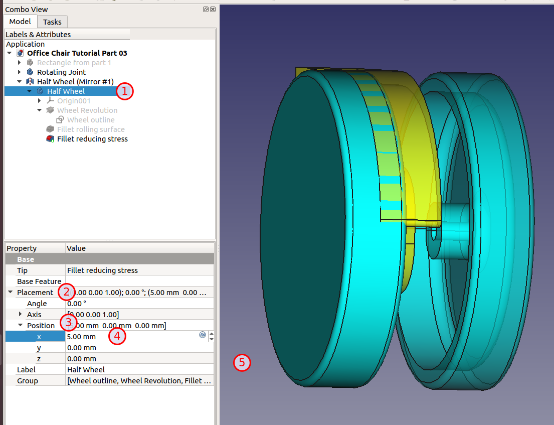
Already much better. Both wheels moved away from the origin by changing only a single value. Neat.
That leaves us with centering the joint.
Open “Rotating Joint”, double click “Pad”
Check “Symmetric to plane”

to get:

Nice. From the top:
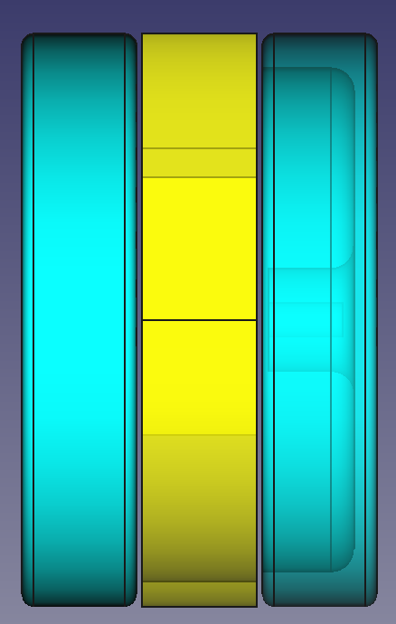
No contacts all the way through. But we have an ugly hole when looking at it from the right:
That asks for a bigger fillet. Try 5 mm:

Last step: The rotation axis of the joint (at the top).
The result should look like this:
Pad to 45 mm:
Change the node name to “Vertical Joint Axis”
Select the top circle and click the “Chamfer” too to get:

Finally, let’s cut a ring into the vertical axis so we can use a spring to keep it in the socket.
Rename it to “Groove Outline”
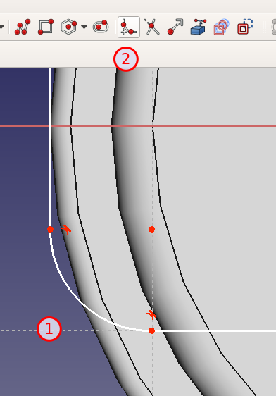
Next, I need to rotate this “Groove Outline” around the center axis of the cylinder. There is no such axis but we can create one. In the “Part Design” workbench is a tool “Datum line” for this purpose.
Click on the circle where the cylinder and the joint meet (1) to get a faint yellow line (2):

This gives us the rotation axis that we need. Click OK to save the new “DatumLine”. Rename it to “Vertical Rotation Center”

and you should already see the groove. Click OK and we’re done:

Here is the file so far: Office Chair Tutorial Part 03
Next part: FreeCAD Tutorial Office Chair Part 4: Five Struts and One Receptacle
3 Comments | Software, Tutorial | Tagged: CAD, FreeCAD, Software, Tutorial | Permalink
Posted by digulla
Here is part 1: FreeCAD Tutorial Office Chair Part 1: Setup and Constraints
What’s an office chair without wheels? A wreck. So let’s give them some:

And done. In our next part, we’ll see how we can create the whole foot (two wheels with an axis and a rotating joint to attach to the base) … What?
All right.
As with the rectangle from part 1, we need an outline for the wheel. But before we can start, what should we do with the rectangle itself? We could delete it or create a new project or rename it. I suggest to rename it so you have something handy where you can play around.
Select the node “Body” and press F2 or right click and select “Rename”. Just start typing the new name. That solves half of the problem.
With that out of the way, we need a new body for the wheel. Make sure you’re in the “Part Design” workbench

“Part Design” workbench selector
and click “Create new body”. You might get an error:

That happens when you create a new body while another is currently “active”. Most operations work on the active body. That way, you don’t have to select the target of your operations all the time. Just click OK to get a new, active “Body001”.
Rename it to “Half Wheel”. Why half? It’s good practice to be lazy. Since most chairs have symmetrical wheels (one on each side of the joint), we’ll just draw one of them and then ask the software to create a mirror copy:
Neat, right?
With the body “active” (= the name is bold), create a sketch. If the “Half Wheel” isn’t active, double click on it.
Again, we chose the XY plane:

Hm. I don’t know about you, but I don’t want to see the rectangle while I’m working elsewhere. If we could just hide it … yes, we can.
Go back to the “Model” tab, right click on the rectangle node and select “Toggle visibility” (shortcut: Space):
Much better! Pick the polyline tool and create a rough outline:

The bottom will become a hole for the axis of the wheel, the top is the surface on which the wheel is rolling. As you can see, FreeCAD already created a ton of constraints: Horizontal, vertical and “fix point on object” ones. In my case, it’s already complaining:

I clicked on the link in the solver message “(click to select)” and the offending constraints are green. It’s a vertical constraint in the top left and a horizontal constraint in the bottom right.
I could delete them but I feel those constraints are correct. Instead, the “fix point on object” constraints might be wrong because my outline has no freedoms left in it. If I pick the right side, I can’t move it because the bottom point is nailed to the X axis. Since the dimensions are most certainly wrong, this is bad. Also, the wheel will be stuck in something. Imagine an axis going through the origin. This axis will be in some kind of holder. If the wheel touches the Y axis, it will probably touch whatever holds the axis. We don’t want that kind of grinding, so we have to move the four points on the Y axis away and the “point on object” constraints prevent this.
Let’s delete all of these constraints:

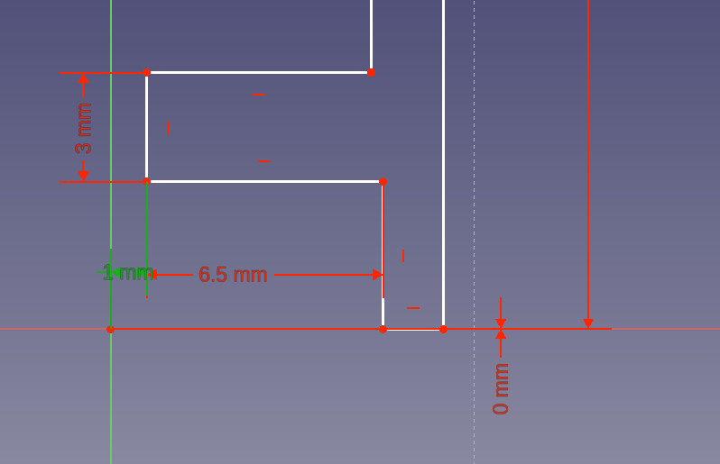
Ah … freedom. Ahem. Let’s start with some simple constraints to get the sizes roughly right. The rolling surface will take all of the weight, so let’s give it 3 mm. The same is true for the material holding the axis. The “side” of the wheel will just take pressure along the material (no torsion), so it can be 2 mm. To save material on the (metal) axis, let’s not extend it all the way out to the side of the wheel. Let’s make the wheel 10 mm thick and 50 mm tall. With these dimensions, we can make the hole for the axis 6.5 mm deep. Deep enough for a good hold:

Note that the height is half of 50 mm = 25 mm.
But it doesn’t look great. Click on the dimensions (the numbers) and drag them until you can read everything properly:

Much better. The 2 mm at the top isn’t great but good enough for now. Let’s move the wheel outline to the correct position. The two bottom dots should be anywhere on the X axis. To achive this, select one of them and the origin and constrain the vertical distance to 0 mm:

Above, we said that we want the wheel to be away from the holder of the axis. Select one of the two vertical points near the bottom left and constrain the horizontal distance to the origin to 1 mm:

sigh Wrong way again. To fix:
While dragging the line, you’ll notice two things:
FreeCAD tries to do what you want with the least amount of change.
Let’s finish the hole for the axis. For this, we need to assign a height. For a 3 mm axis, this would be 1.5 mm. Which we could calculate in our head but how about an axis which is 7.125 mm? To spare use the humiliation, let’s use the little “f(x)” button in the text box. The formula would be “3/2”:
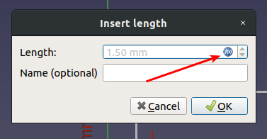
Nice:

To denote the fact that this is a calculated value, the constraint has an orange color. This leaves me with a single degree of freedom left. If you look closely, you’ll see that the bottom and top parts have different widths. If you click on the outline and drag it, you can see that the freedom is only in the length of the horizontal lines at the bottom. There are different ways to fix this:
I’ll go for the last approach because that allows us to easily modify the width of the wheel and the gap between wheel and axis holder and, later, the top cover of the wheel:
 I used a 0.5 mm horizontal constraint.
FreeCAD is happy with the result and so am I. Close the outline to go back to the “Part Designer”
To turn the outline into a wheel, use the tool “Revolve a selected sketch”. The sketch should be selected; if not, make sure it is:
Now that doesn’t look right:

By default, FreeCAD rotates around the vertical sketch axis (see the “Axis” combobox). Change that to “Horizontal sketch axis” and you have a wheel:
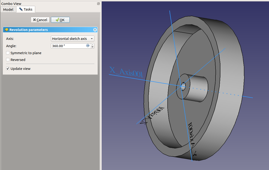
Make sure the rotation angle is 360 (= full circle) and “Symmetric to plane” and “Reversed” are both off.
After clicking OK, our tree looks like this (I’ve opened the “Revolution” node):

As you can see, FreeCAD remembers our operations: We started with the sketch (outline), then rotated it.
As wheels go, this one is nice but the edges are too sharp. They would feel bad to the touch and would easily break (they would also be very hard to produce). Let’s round them. Select the rim and click the fillet tool:
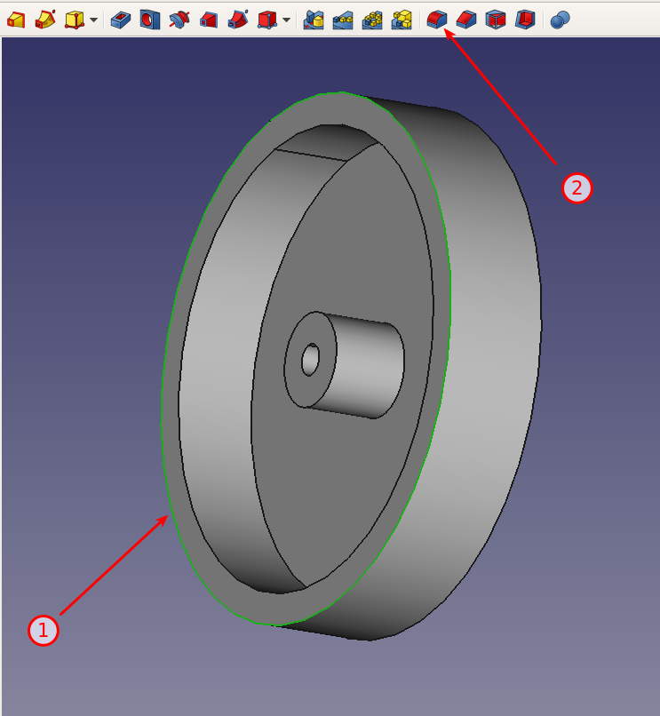
That looks much nicer:

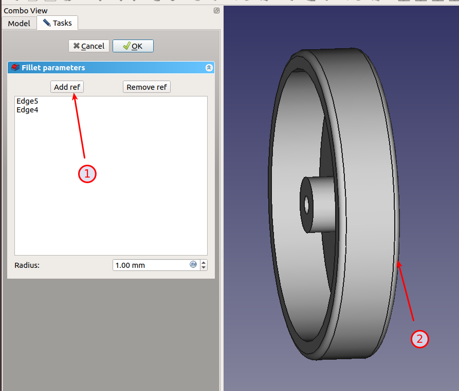
Since we want the same fillet on the outside, click “Add ref”, select the other rim to get:
Now for another fillet on the inside (1) with a radius of 3 mm (2):

Too much? Double click “Fillet001” and change the radius to 2 mm:

Now, I want the same on the axis hole. Double click the fillet again and add the additional edge:

All right. This looks like a nice wheel which won’t break easily:

Note that I’ve renamed most nodes to make it easier to tweak the design later.
Project file: Office Chair Tutorial Part 02
Next part: FreeCAD Tutorial Office Chair Part 3: Mirrors and Holes
3 Comments | Software, Tutorial | Tagged: CAD, FreeCAD, Software, Tutorial | Permalink
Posted by digulla
After starting FreeCAD 0.18, you’re greeted with this windows:

FreeCAD main window
At the top are the toolbars, on the left side are the current model tree and in the center is the main work area.
The main work area contains a tab “Documents” where you can start a new project and see your recent ones and a tab “Help” which gives you access to the online help. If you have two monitors, I suggest to open a web browser on the second screen and open this URL: https://www.freecadweb.org/wiki/Getting_started
Please read the part about “Navigating in the 3D Space” so you know how to move (pan) the drawing board and how to rotate it and, more importantly, how to reset it to a sane state 🙂
Let’s start with a new project. Click “Create new…” in the “Documents” tab.
This creates an unnamed project. To give it a name, save the file using “File” / “Save…”.
FreeCAD has several main concepts. Let’s look at two of them: Sketch and Part. A sketch is the outline of something. After designing it, you can use a 3D operation like “pad” (often called “extrude” in other software) or “revolve” to create a 3D body from the outline. Other operations cut holes into parts or arrange then in patterns.
The result of all those operations on parts is called “body”.
In order to create our wheel, we need a body, first. To create one, select the “Part Design” workbench:
“Part Design” workbench selector
This will give you a new toolbar:

Create body icon
The first icon is the one we want. It will add a node “Body” to the tree with a child “Origin”. This child is the coordinate system of the body. Each body has their own (since they are independent of each other).

Tree with the first body
Tip: Try to design your bodies in such a way that the “handle” (= the must useful point to place the body) is at the origin (0,0,0).
Now that we have a body, we can create our first outline using the second icon. FreeCAD will switch from “Model” to “Tasks” and ask for the plane in which you want to draw:

Select plane in which to draw sketch
FreeCAD is a 3D CAD software but editing 3D with a 2D mouse is tedious and error prone. To work around this problem, the designers of the software came up with a trick: They let you draw the outline of a shape and then give you tools to turn the outline into a volume.
For our wheel, we’ll draw the outline and then rotate it around the wheel’s axis to get a complete wheel.
You will now have to decide in which plane you want to draw the outline. If X is “left-right” and Y is “up-down”, then Z is “closer-farther”. This gives you three planes: XY (what we all used in school), XZ (horizontal or ground plane) and YZ (vertical but perpendicular to XY).
For example, you could think that the wheel stands on the ground, it’s axis parallel to the X axis, and you’re looking down on it. If you think like this, the most natural approach is to cut the wheel horizontally and remove the top part. Now you can see the outline of the wheel in the in the XZ plane.
Or you can think of the wheel as standing in front of you. Now, we cut it vertically along the XY plane to get an outline.
Or you can think of looking at the wheel from the side. In this case, the outline would be in the YZ plane.
Let’s start with XY (XY_Plane) just like in school. After clicking OK, you’ll see the “Sketcher” workbench:
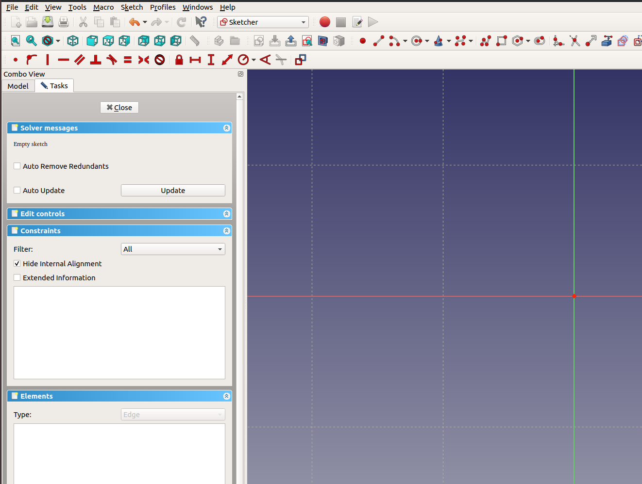
Sketcher Workbench
All this workbench switching probably feels a bit scary. The advantage is that you won’t see thousands of icons.
Tip: You’ll be working a lot with constraints. To make your life easier, pull down the constraint toolbar down like I did to be able to see all icons at once.
To the left are now three panels under “Tasks”: Solver messages, Constraints, Elements.
Elements is a list of basic shapes that make up the outline. That can be lines, arc, circles, polylines, etc.
Constraints lists the properties which must be fulfilled to create a “correct” outline. For example, if you have two lines which must be parallel, the output is wrong when the lines are skewed.
FreeCAD uses a “solver” to determine the correct outline. The topmost panel is used to keep you informed about the success or failure of this process.
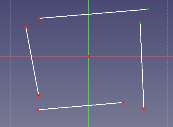
Confused? Let’s start with a simple example and create a rectangle from four lines. Click the “Create a line” tool (shortcut: L). Now click for the first point, move the mouse, click again for the second point. Repeat 3 times to get four lines like so:

Note the little red line next to your cursor. This tells you that the tool is still active. To deactivate it, click the right mouse button once.
But that’s not a rectangle, you say. Why not?
Well, first of all, the corners should be closed. To fix this, I use the “Coincident Constraint” (shortcut: C). Select two points that should have the same position. There are two ways to do this:
To clear the selection, click on the blue background of the drawing.
Afterwards, you should have two green points and 7 red ones (6 line ends and one origin):
Click on “Coincident Constraint”:

Two things happen:
Click on the new corner and drag the mouse around to see that the endpoints of the two lines are in fact “connected”.
Repeat with the other three:

Still not a rectangle but closer. What else defines a rectangle?
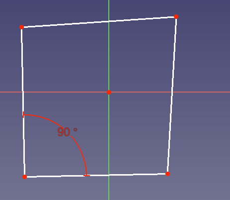
90° angles in the corner. Let’s add this constraint as well. First, select two lines with a common point by clicking on them to turn them green, and then on the “Constraint Angle” icon (1) to get a new dialog which asks for an angle:

As you can see, the tool offers the current angle as default which is great if you just need a small adjustment. Enter “90” and close the dialog with OK. You’ll see a new “Constraint5” in the list with “(90 °)” behind it but the result looks off:
What happened? Well, FreeCAD just made sure those two lines are now at a 90° angle with respect to each other. It didn’t rotate the whole rectangle. This allows you to create rectangles at all angles. To fix the right side, let’s make it parallel to the left side. Select the two sides and click the “Constraint parallel” (icon with two diagonal parallel lines):

Note “Constraint6” plus the small icons next to the vertical lines.
Also notice that the rectangle rotated. Annoying, isn’t it? But we didn’t tell FreeCAD where the rectangle is supposed to be, so it shifts it around to make our demands work.
One side left. To fix it, we have three options:
Since less is more, we’ll just add another parallel. But keep in mind that there is often more than one way to get to a result:

Finally, a rectangle (almost a square). But if you look at the “Solver messages” panel, it says “Under-constrained sketch with 5 degrees of fredom”. What does that mean?
It means that while it’s a rectangle, that’s not good enough for CAD purposes. For example, it has no defined width or height. Imagine buying a car where you don’t know the size in advance!
Let’s create a rectangle with is 7.5 mm tall and 12 mm wide.
Select the left side, then click “Fix a length of a line” (1):
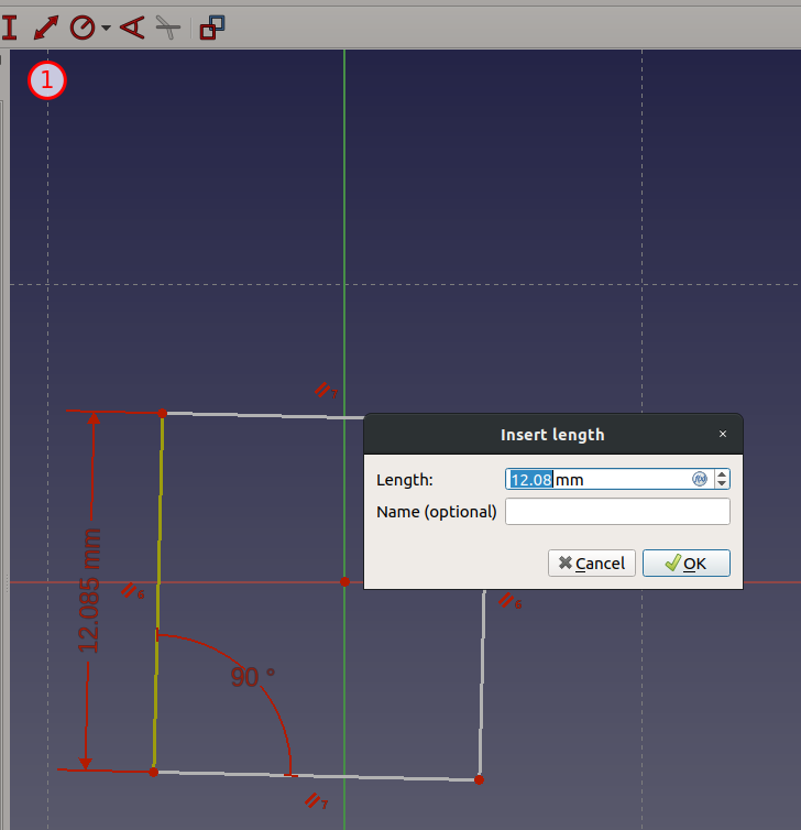
Enter “7.5” and click OK.
You will notice that both the left and right side of the rectangle changed their lengths (and it jumped). This is because of our parallel constraints: FreeCAD will keep the shape for us, even when things change!
Set the width to 12 mm in the same way:

This gets us down to 3 degrees of freedom. In our case, that the X and Y position of the rectangle and the orientation.
It’s good practice to define a “handle” or “attachment” point. In our example, let’s say that the bottom left corner is our attachment point. This point should be at the origin. Select the origin (click on it or use the menu item “Sketch” / “Sketch Tools” / “Select origin”; shortcut: Ctrl+Shift+O), then the bottom left corner of the rectangle and finally “Coincident Constraint”:
To get a feeling how the constraints work, grab a side or corner and drag it around. See how the rectangle keeps it’s shape and only rotates around the bottom left corner?
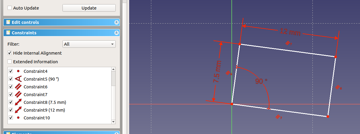
Almost done. Add an angle constraint of 17.5 ° between the X axis (just click the horizontal line) and the bottom edge:
What happened? Why is it going “down” instead of “up”?
FreeCAD doesn’t count angles from the X axis. It just keeps the angle between the two selected lines by moving everything the least amount. In this case, the downward direction was “closer” and therefore, it used this solution. If you want the other result, delete the constraint (or use undo), rotate the rectangle up and try again:

Note that the whole outline turned green to indicate that it’s properly defined, now.
In the Solver panel, you can see “Fully constrained sketch”.
To finish the outline, scroll up in the “Tasks” panel and click “Close”:

Final result as download: Office Chair Tutorial Part 01
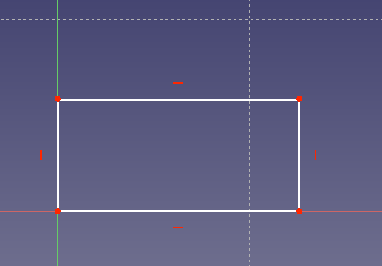
Over time, you’ll find better and faster ways to do things in the software. Let’s try it. Draw a rectangle instead of four lines:

Note that the software already filled 8 constraints for you. Constrain the left bottom edge to the origin:
Constrain width and height as above:

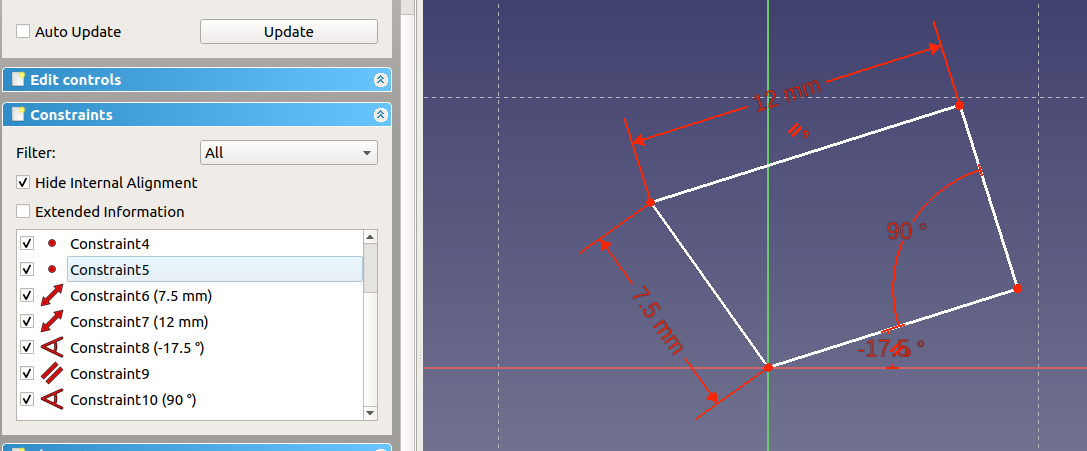
And assign an angle of 17.5 ° to the bottom line:

Hey! What’s wrong?
Well, there is a constraint that the bottom edge is parallel to the X axis (the red dash). It’s either Constraint 5 or 6. The solver tells us “Over-constrained sketch” and, helpfully, “Please remove either constraints 6 or 12”. Also, there is a dialog “Negative datum values are not valid for the constraint with index 11”.
The dialog is confusing and not very helpful. Sorry for that. Just close it.
Huh? Everything is fine?
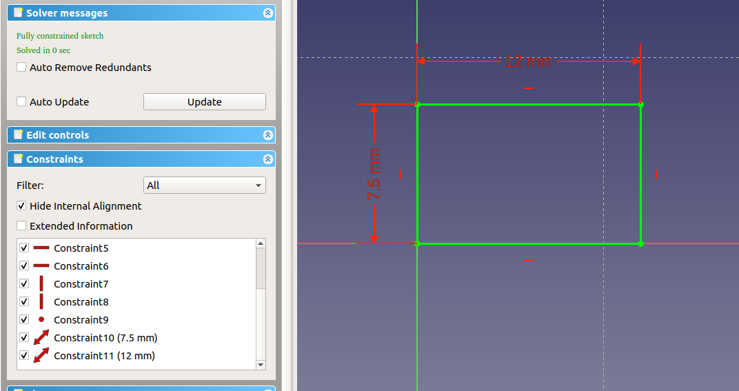
Oh, it just deleted the angle constraint! That’s not what we want. But it already gave us a clue: The “bottom must be horizontal” constraint is #6 (from the error message above). Delete it and try again with the angle constraint:

Well … almost 🙂 Double click on the angle and change it to “-17.5 °”:

We’re getting there. Delete constraint 5 and make top and bottom parallel:
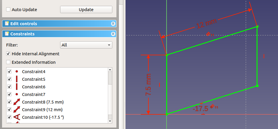
A parallelogram (or rhomboid)! Do you feel the power of the tool? How it tries to fulfill your expectations? Remove the vertical constraints and drag an upper corner of the rectangle around. You probably thought it would slide sideways but instead the corners “rotate” around their bottom counterparts. If you pick the right bottom corner, you can only slide it along the bottom edge, shortening or extending it in the process. That’s what FreeCAD means when it says “2 degrees of freedom”.
To fix this, you need to apply the rules of rectangle (all four corner angles must be 90 °). Let’s start by using a 90 ° constraint in the bottom right corner:
Close. To get the same result as before, we either need to assign another 90 ° constraint or make the left and right side parallel. Let’s add a angle constraint in the top right corner:
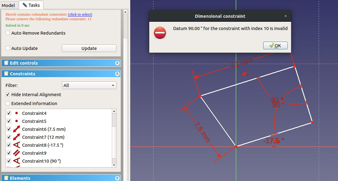
A new error: “Sketch contains redundant constraints” and (another) useless dialog “Datum 90.00 ° for the constraint with index 10 is invalid.” What happened? We have a parallel and two 90 ° constraints. That’s too much; either two 90 ° constraints or one parallel plus one 90 ° constraint would be enough to achieve the same result. In a nutshell, FreeCAD tries to help us avoid unnecessary constraints. For one, they are futile and secondly, they might get in the way later when we want to change something. Clicking OK in the dialog and our angle constraint will be gone. Two to put the 90 ° angle into one of the two left corners:

All right. Same result as above but using a different route. This time, we made more “mistakes” which helped us to understand how constraints can both help and hinder us.
Office Chair Tutorial Part 01 Two Rectangles
In the next part, we’ll use constraints to define the outline of a chair wheel. FreeCAD Tutorial Office Chair Part 2: Wheels
4 Comments | Software, Tutorial | Tagged: CAD, FreeCAD, Tutorial | Permalink
Posted by digulla
Instead of encrypting everything with a single government key, several government agencies need to provide new public keys every day. The private key must be under the control of a court. Each secure encryption channel needs to subscribe to one or more of those agencies. The court must delete those keys after six months.
Advantages:
Disadvantages
Always remember that in a democracy, the law isn’t about justice but balancing demands. There are people afraid that embarrassing details of their private communicate will be exposed as well as people trying to cover the tracks of a crime.
Right now, there is no better way to determine which communication needs to be cracked open than a normal court case.
Reasoning:
If we used one or a few keys to encrypt everything (just because it’s easier), that would put a huge attraction on this data. Criminals will go to great lengths to steal those. If there are many keys, each one of them becomes less important. The amount of damage each key can cause must be smaller in this case. It would also mean they would have to steal many keys which would raise chances to get caught.
I was wondering if one key per month would be enough but there is really no technical reason to create so few. We have the infrastructure to create one every few seconds but that might be overkill. Once per day or maybe once per hour feels like a sweet spot. Note: When the technical framework has been set up, it should be easy to configure it to a different interval.
If we spread the keys over several organizations, an attack on one of them doesn’t compromise everyone. Also, software developers and users can move around, making it harder for unlawful espionage to track them.
Police officers and secret services should not be left alone with the decision what they can watch. Individuals make mistakes. That’s one reason why you talk to a friend when you make important decisions. Therefore, the keys should be in the hands of the law.
The law isn’t perfect. My thoughts are that we would use the perfect system if it existed. Since we’re using the law, the perfect solution probably doesn’t exist or it doesn’t exist, yet. In either case, using court rulings is the best solution we have right now to balance conflicting demands. The keys could be confiscated when the case is started and destroyed when the case is closed to avoid losing access halfway through the proceedings.
Mistakes will happen. Systems will break, keys will be lost, important messages will become indecipherable, criminals will attack the system, idiots will put keys on public network drives. Is there a way that this can be avoided? I doubt it. Therefore, I try to design a system which shows a certain resilience against problems to contain the damage.
For example, a chat app can request keys from its source. If that fails, it has options:
Leave a Comment » | Philosophy, Software | Tagged: Encryption, Key Escrow, Patently Unpatentable, Security | Permalink
Posted by digulla
Leave a Comment » | Game | Tagged: Game, Recommendation | Permalink
Posted by digulla

EU Copyright Reform Art 11&13
22. March, 2019The reform in the current form was designed to increase profits of the big players in the game: the few big music labels, movie companies and news agencies.
Since they want those additional billions, I think it’s moot to argue against the reform. If we stop them this time, they’ll be back next week.
Instead, I suggest to change the reform to force them to provide online services to license their content.
A few clicks and you’re allowed to use a piece of music or video or text for your own work. Yes, it will cost money but videos don’t grow on trees, either.
That way, the poor mega companies on this planet look good in front of their shareholders and the people creating art don’t have to waste money on fending off lawsuits.
Oh, and maybe add a clause in the law that the companies have to pass a real amount of money on to the artist. Right now, they are actively being starved by the companies (except for a few topstars who could afford the lawyers to get their share).
Share this: